Six years ago, on May 30th 2018, the TESS spacecraft executed a Period Adjust Maneuver (PAM) to insert the spacecraft into its final 2:1 Lunar Resonant mission orbit. This concluded a series of maneuvers after launch on a SpaceX Falcon 9 that targeted a Lunar flyby to swing the orbit plane out of the ecliptic plane and avoid long duration eclipses for more than 18 years.
Missions like TESS have the potential to return valuable science for decades, as long as the spacecraft can survive. Careful mission design can greatly increase the chances of mission survival beyond primary mission completion. The 2:1 resonance of the TESS orbit removed any need for orbit station keeping, allowing for long-term prediction of eclipse durations. Monte Carlo analysis during operations then enabled the flight dynamics team to actively target PAM to avoid any that could be mission-ending.
TESS is now in its second extended mission after 6 highly-productive years of exoplanet discovery! SEE’s Ryan Lebois and Craig Nickel supported NASA Goddard Space Flight Center (GSFC) during the mission design and operations of TESS through successful mission orbit insertion.
Learn More
Read Ryan Lebois and Craig Nickel’s conference paper to learn more.
April 18th marks 10 years since the NASA LADEE mission successfully ended with an impact to the lunar surface! The NASA Ames Research Center (ARC) led this mission, which carried three instrument payloads and one tech demo – the Lunar Laser Communications Demonstration. The mission operated successfully through its planned science phase of 100 days and an extended mission phase of 45 days, with the last few weeks spent operating at an extremely low altitude to enhance science collection.
SEE’s Lisa Policastri served as the Orbit Determination Lead throughout all phases of mission development and mission operations, including during the final shift on console at the ARC multi-mission operations center when LADEE impacted the Moon at the Sundman V crater rim at a velocity of 3,600 miles per hour.
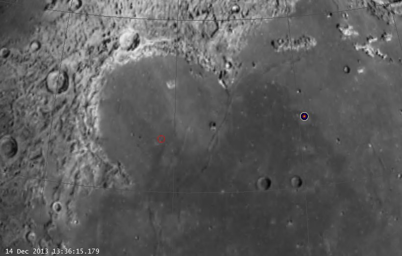
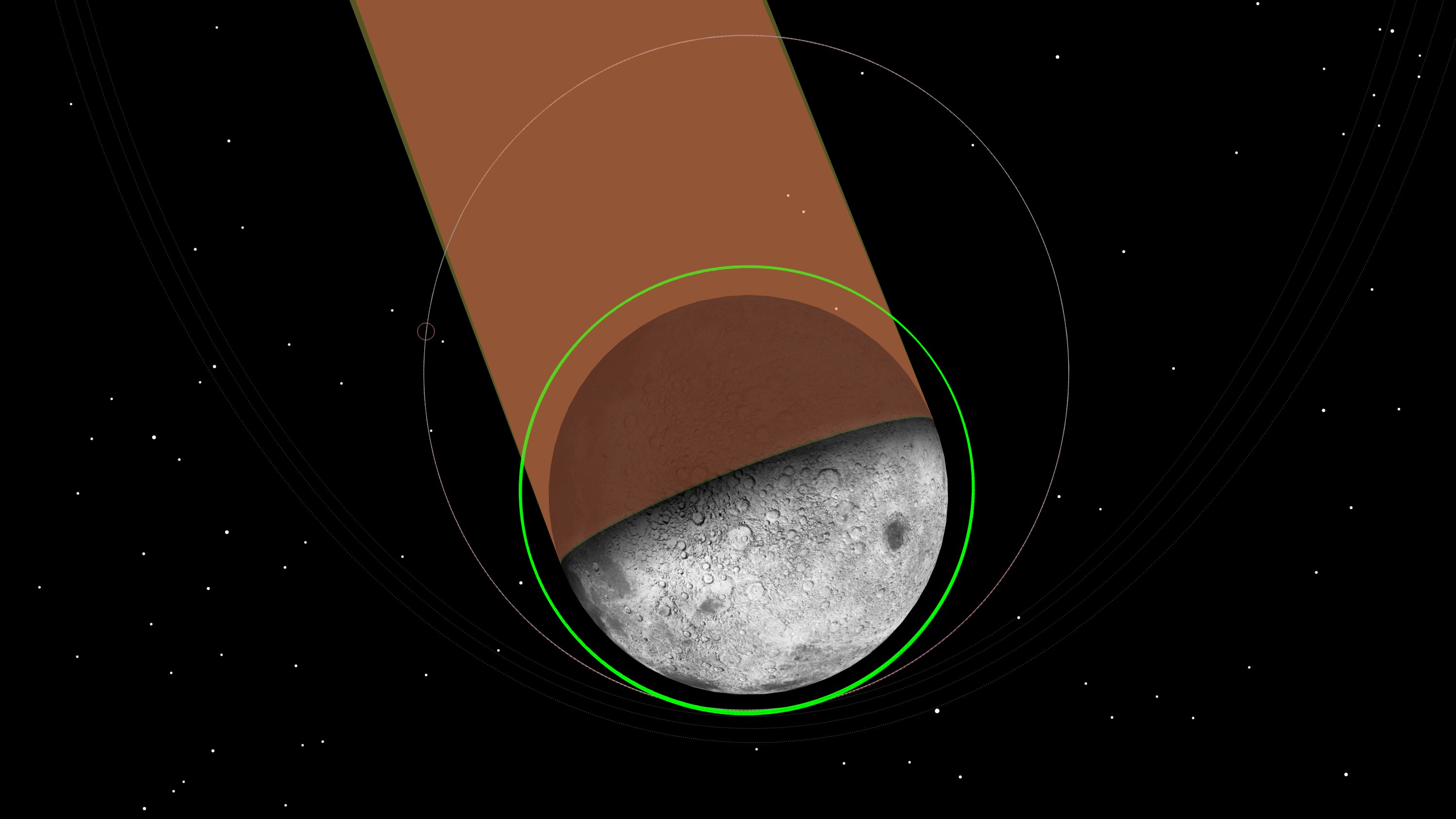
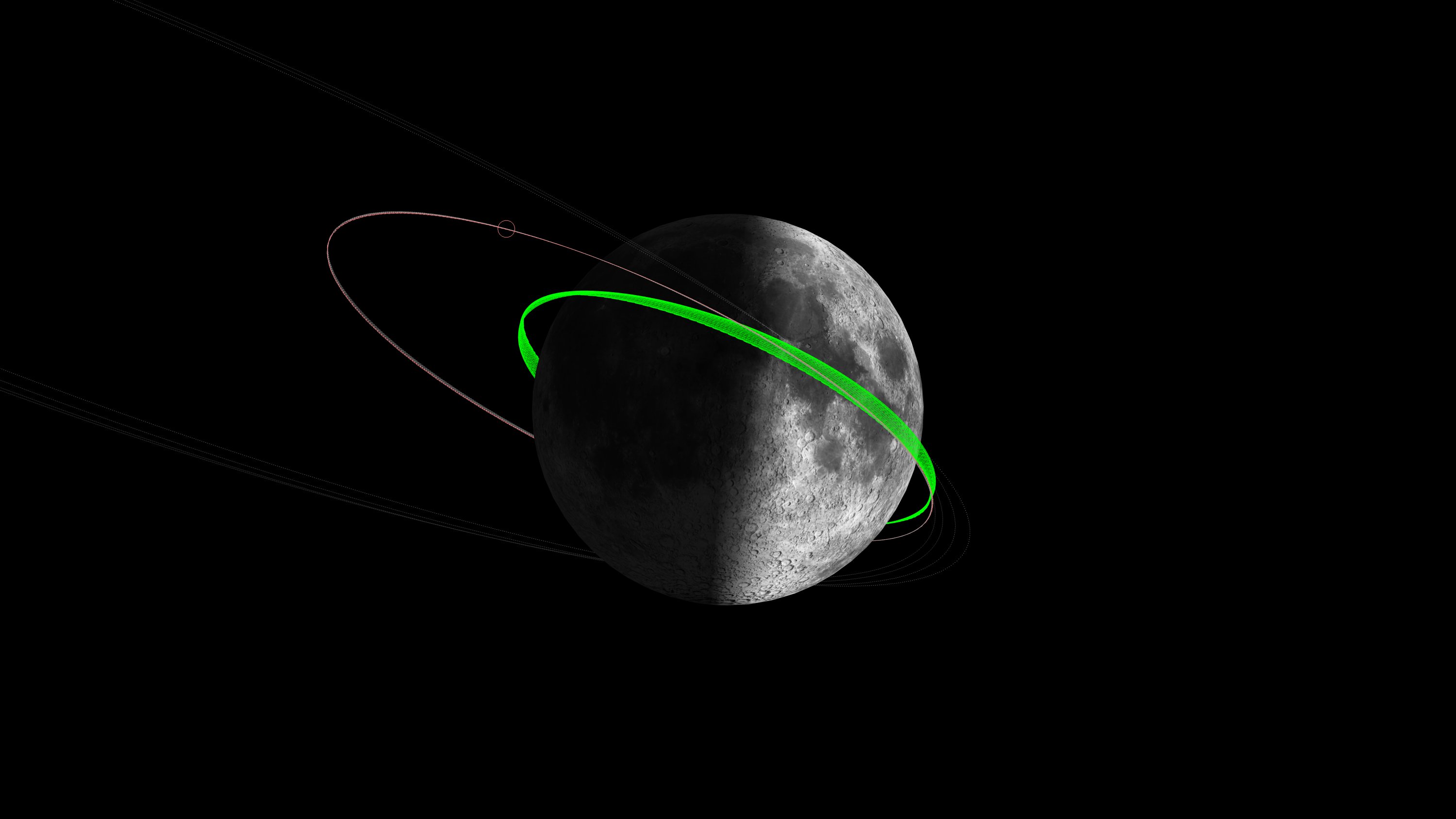
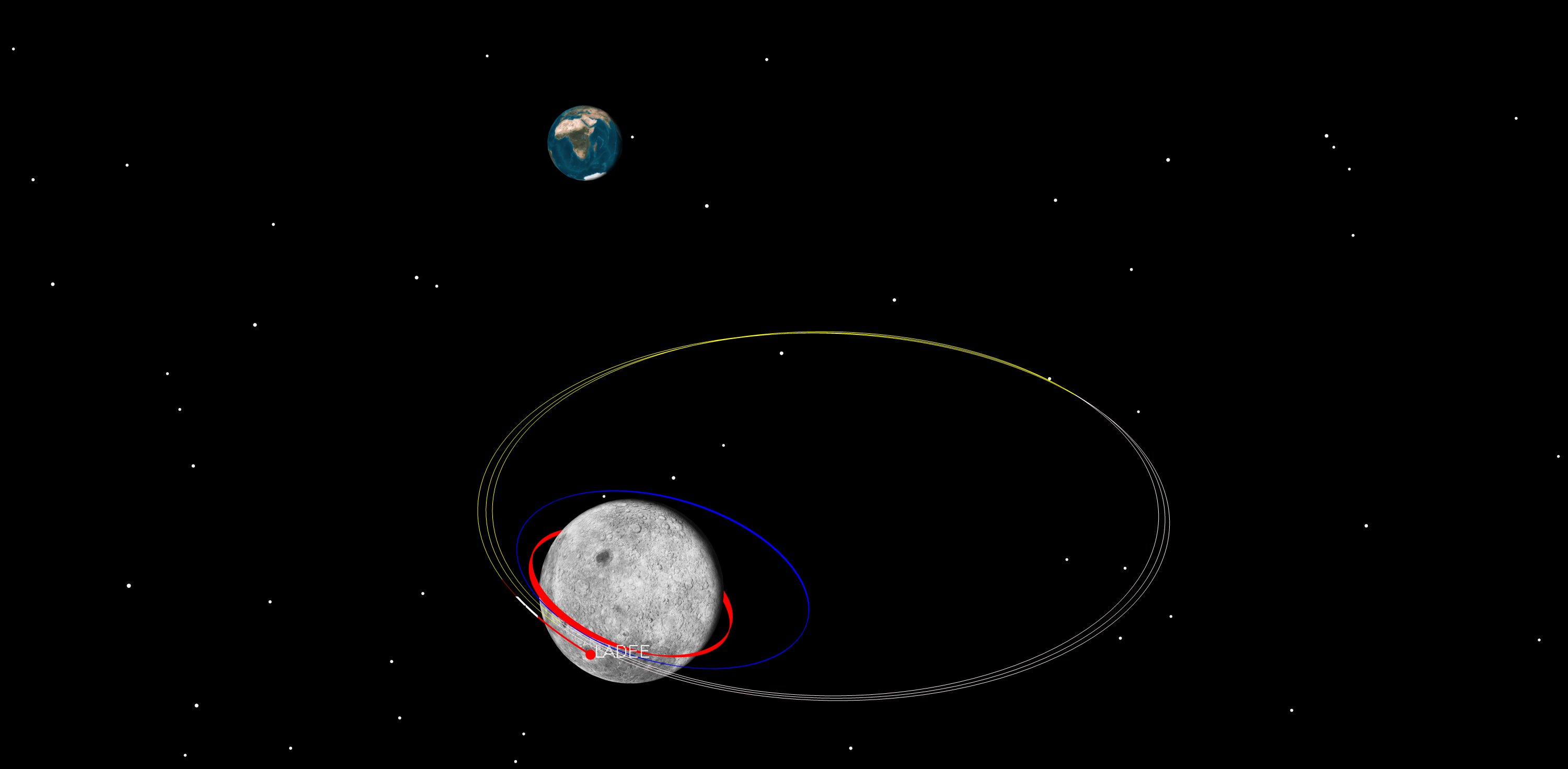
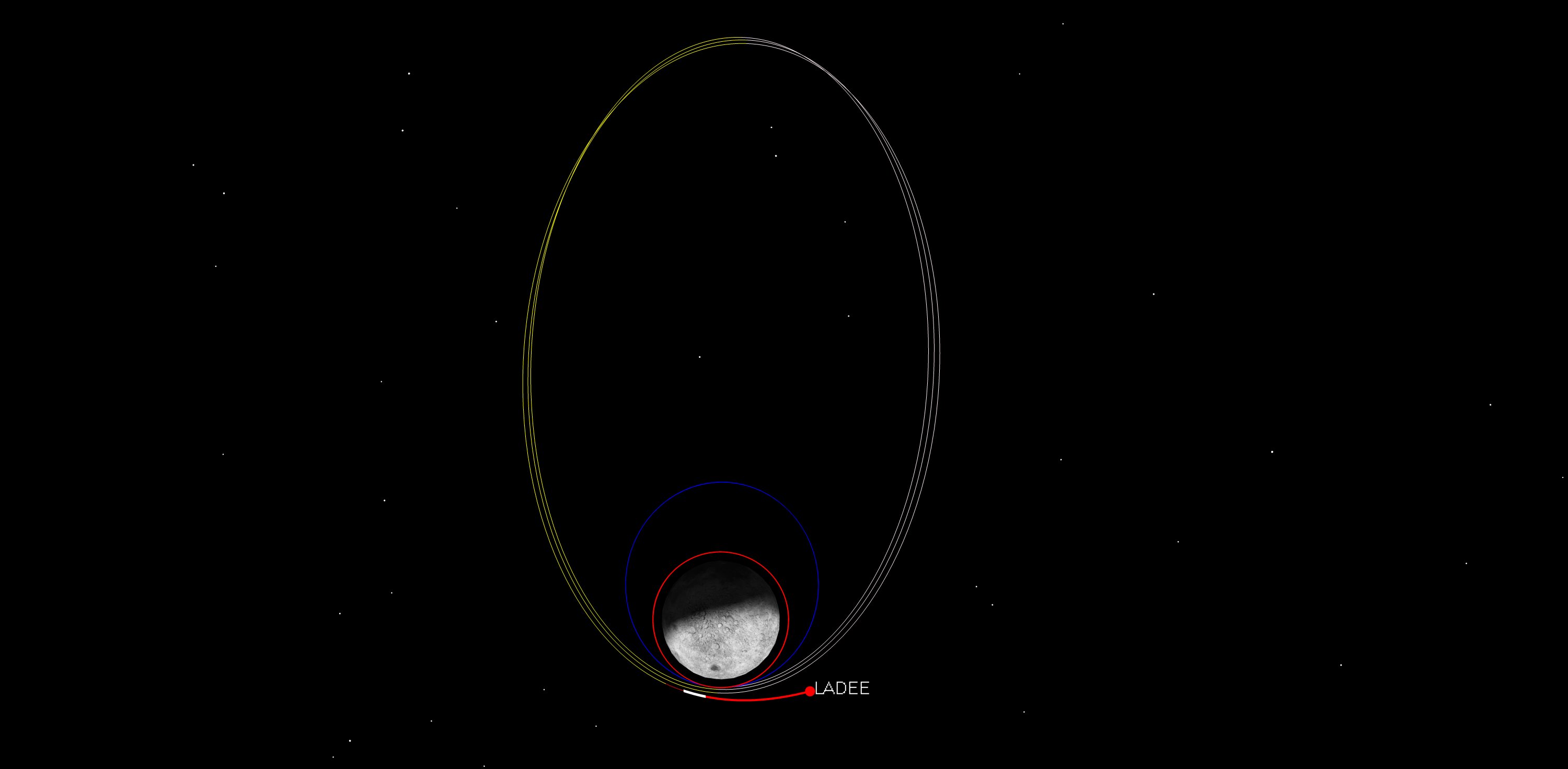
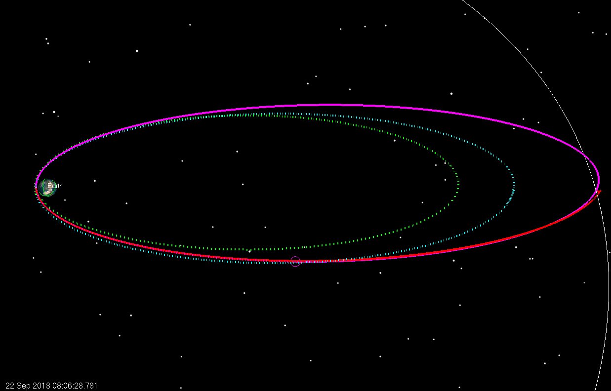
The image below, from our 2014 archives, shows our model of LADEE’s position in orbit (red line) with the uncertainty model (red ellipsoid) just before impact at the Sundman V Crater ridge on this day 10 years ago.
This image from our 2014 archives depicts our model of LADEE’s orbit (red line), along with the uncertainty model (red ellipsoid), just before impact at the Sundman V Crater ridge, exactly 10 years ago today.
Later in 2014, the Lunar Reconnaissance Orbiter Camera confirmed the location of LADEE’s impact.
This shows LADDEE’s impact site, near the Sundman V Crater.
This video shows the last orbit of LADEE up to impact.
NASA’s 2014 article titled “NASA’s LRO Spacecraft Captures Images of LADEE’s Impact Crater” states, ” ‘The Lunar Reconnaissance Orbiter Camera (LROC) team recently developed a new computer tool to search Narrow Angle Camera (NAC) before and after image pairs for new craters, the LADEE impact event provided a fun test,’ said Mark Robinson, LROC principal investigator from Arizona State University in Tempe. ‘As it turns there were several small surface changes found in the predicted area of the impact, the biggest and most distinctive was within 968 feet (295 meters) of the spot estimated by the LADEE operations team. What fun!’ ”
In addition to Lisa, many current SEE team members were heavily involved in the LADEE mission’s success, including Mike Loucks, John Carrico, Craig Nickel, Alisa Hawkins, and Ryan Lebois. The entire LADEE mission operations team was a truly amazing group! No one slept much during those final days – everyone relied on strong teamwork and lots of caffeine and snacks!
Lisa Policastri on the Day of the LADEE Impact: April 18, 2014
Today we have been reflecting on an impactful experience that happened on this day, March 14th, in 2008!
After a failure of its Briz-M upper stage shortly after launch on March 14, 2008, the AMC-14 communications satellite was left stranded in an inclined geostationary transfer orbit. John Carrico and Mike Loucks developed a recovery trajectory to deliver the spacecraft to its originally intended orbit.
Changing the angle between a spacecraft’s orbit plane and the equator is expensive in terms of propellant. Since AMC-14 was stranded near an inclination of 52 degrees, propellant could be conserved by boosting the apogee of the spacecraft’s orbit out to lunar distance.
Two lunar encounters (a “double lunar swingby”) reduced the inclination to 0 degrees (an equatorial orbit) and raised perigee to GEO altitude. Perhaps counterintuitively, the propellant required for these large changes in altitude was less than that required to reduce inclination propulsively.
Ultimately, AMC-14 did not utilize a double-lunar swingby trajectory to reach GEO. Instead, a series of low-thrust maneuvers were performed to raise orbit and eventually reach an inclined, geosynchronous orbit.
Double lunar swingbys are one of the “tools” in the astrogator’s toolbox. For resource constrained missions, lunar gravity assists can enable large orbit changes while conserving propellant. Every day, the SEE team applies techniques like this to solve challenging mission design problems!
30 years ago yesterday, the Deep Space Program Science Experiment spacecraft, dubbed “Clementine,” entered lunar orbit after executing the Lunar Orbit Insertion (LOI) maneuver to place it into a 426.9 km x 5485.1 km orbit, with an orbit period of 8 hours.
Originally launched on a Titan II(23)G rocket from Vandenberg Air force Base launch site SLC-4W on January 25, 1994, the spacecraft used an R-4D 490 Newton engine to perform the insertion. The R4D used bipropellant hydrazine (N2O4/MMH) with an Isp of 310 sec.
The LOI maneuver was planned using the software tool “Swingby” at Goddard Space Flight Center. SEE founder, Astrogator John Carrico, was on the team that both developed Swingby and used it for maneuver planning on the Clementine mission. Swingby eventually evolved into the STK/Astrogator trajectory planning tool.
Learn More
To learn more read Lawrence Livermore National Laboratory’s article, “The Clementine Satellite.”
Dr. Worden was Director of NASA Ames during both the Lunar Crater Observation and Sensing Satellite (LCROSS) and Lunar Atmosphere and Dust Environment Explorer (LADEE) Missions. LCROSS launched in 2009. LADEE launched in 2013. The SEE team supported both of these missions.
30 years ago today, the Deep Space Program Science Experiment, dubbed “Clementine,” ignited its Star-37FM solid rocket motor to leave low Earth orbit and embark on a 2.5 phasing loop trajectory to lunar orbit. SEE’s CTO, Astrogator John Carrico, was in the frozen flight dynamics facility at NASA’s Goddard Spaceflight Center, keeping a watchful eye on the spacecraft’s trajectory. Clementine returned the United States to lunar orbit after a two-decade absence and ignited a new era of lunar exploration.
Clementine was developed as a unique Department of Defense program to demonstrate dual-use technology in deep space. The mission went from inception to launch in about 22 months for a total cost of $75M. The Naval Research Laboratory designed, built, and operated the spacecraft, turning to the Flight Dynamics Division at NASA Goddard for support during the critical lunar transfer and orbit insertion phases of the mission.
At NASA Goddard, John Carrico was on the team developing Swingby, a trajectory design application tailored for multi-gravitational trajectories. While previously employed for pre-launch analyses on other deep space missions, Clementine was Swingby’s opportunity to support operational trajectory planning and re-design. When a battery anomaly threatened to strand Clementine in LEO, Swingby proved its worth. It enabled the flight dynamics team to deliver over 50 maneuver plans over a span of 8.5 days, often with as little as 12 hours lead time.
Eventually, Swingby evolved into the highly capable Astrogator trajectory planning tool included in AGI STK. The phasing loop lunar transfer pioneered by Clementine enabled subsequent small lunar missions, like NASA’s Lunar Atmosphere and Dust Environment Explorer, SpaceIL’s Beresheet, and Astrobotic’s Peregrine lunar lander. Science data returned by Clementine indicated the presence of water ice at the Moon’s South Pole.
Join all of us here at The Astrogator’s Guild as we celebrate the 30 year anniversary of Clementine’s journey to the Moon and look forward to the next 30 years of bold, inspiring lunar exploration.
When Rocket Lab’s Electron rocket launches the CAPSTONE spacecraft, it will use a series of precisely targeted orbit raising maneuvers and phasing orbits in low Earth orbit to achieve the final injection conditions required to achieve the Ballistic Lunar Transfer that CAPSTONE requires. These maneuvers will be executed by Rocket Lab’s updated “Photon” stage and the plan for these maneuvers will be developed by Rocket Lab’s flight dynamics team. The Rocket Lab Flight Dynamics (FIDO) team consists of Space Exploration Engineering (SEE) and Rocket Lab FIDO engineers who have been training with SEE over the last 2 years. SEE brings a wealth of experience in planning and executing cislunar trajectories of just this type. A big part of our business model is to bring this expertise to our customers so they can continue do these types of projects when the mission is over.
The expertise of SEE’s team comes from missions such as Clementine (DSPSE) which flew in 1994, ISTP(1994), WMAP(2001), IBEX(2008), LCROSS(2009), LADEE(2013), TESS(2018) and SpaceIL Beresheet(2019). All of these missions used combinations of precisely timed Earth phasing orbits and orbit raising maneuvers to achieve their objectives, just as Photon will do to inject the CAPSTONE onto its desired deep space asymptote.
The CAPSTONE Earth orbit profile builds directly from SEE trajectory design and operational experience from a number of previous missions. Each mission design comes from a series of requirements imposed by the launch vehicle (how much mass it can lift to what orbit), the spacecraft propulsion system (how long can burns be, and how many can be done), the navigation techniques used (how many ground passes needed, how big are the antenna on the ground) and operations (how much time does it take to generate new burn plans, process tracking data, generate and test new command files, etc.).
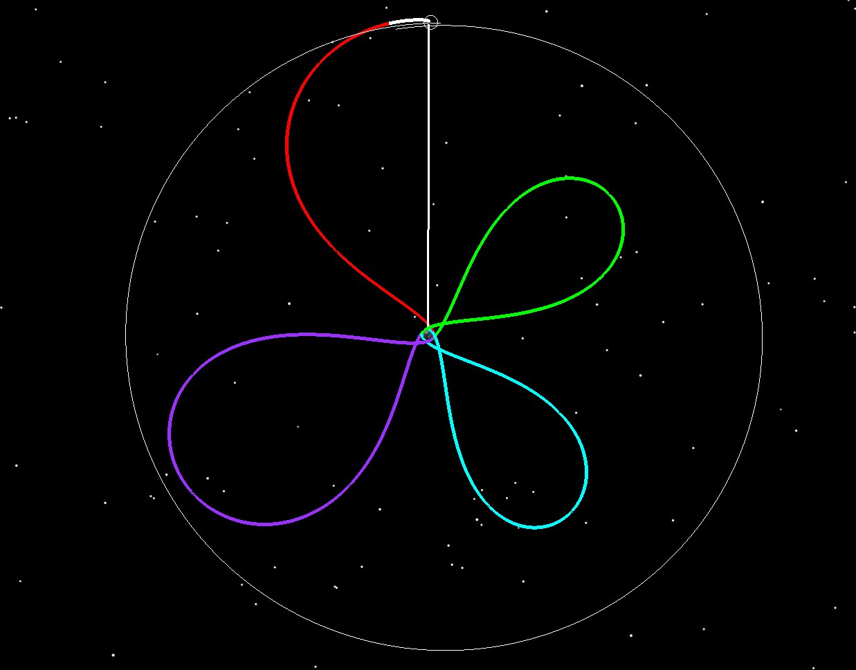
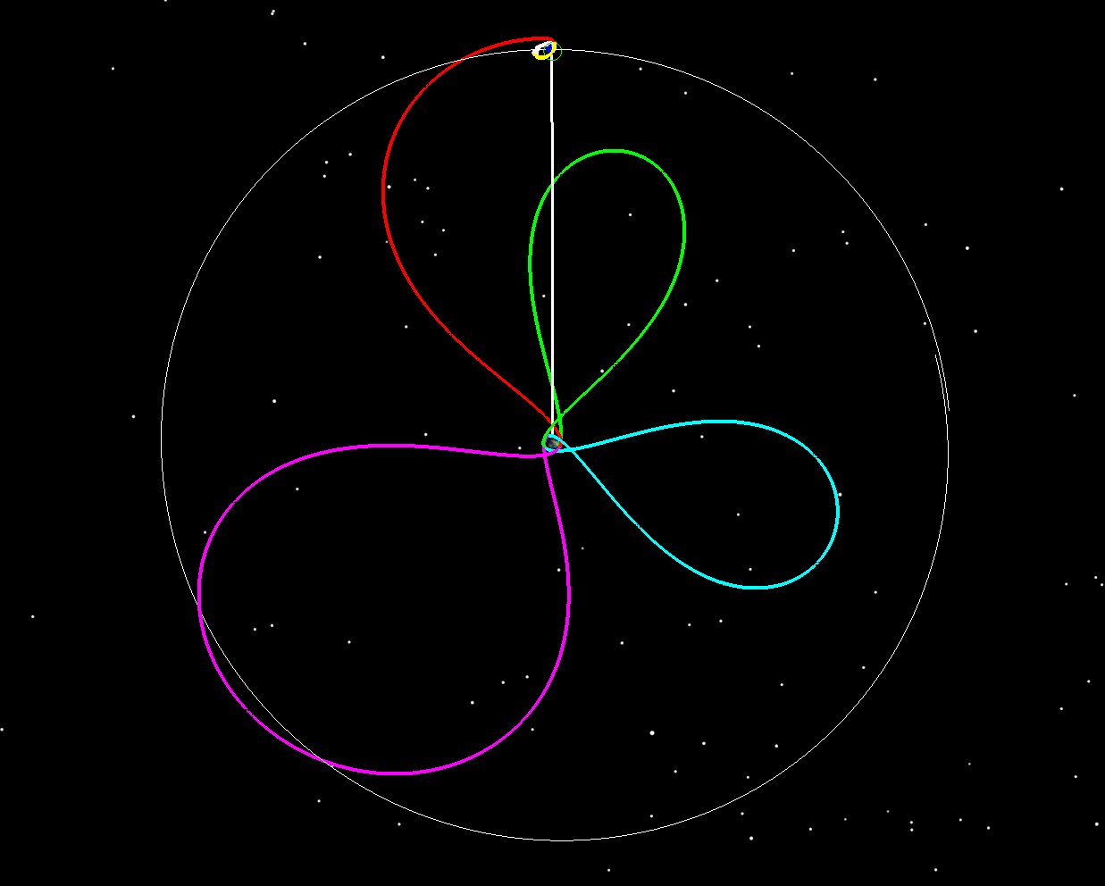
The Interstellar Boundary Explorer (IBEX) trajectory plan was designed, navigated and executed by SEE personnel in 2008. Figure 1 shows the trajectory in an Earth-Moon rotating frame. IBEX used 4 phasing orbits (or loops) to precisely insert IBEX on the desired trajectory in cislunar space. This orbit was ultimately modified to be a 3:1 Lunar resonant orbit that is stable for decades. IBEX is still operational and continues to return good data.
In the Earth-Moon rotating frame, the Earth is in the middle, the Moon is at the top and we draw a line between the Earth and the Moon for clarity. From this vantage point, the Moon appears stationary with respect to the Earth and the background stars appear to rotate.
This frame is useful because it shows you where the apogees and perigees are with respect to the location of the Moon. For a resonant orbit, you want the apogees to stay clear of the Moon. For a lunar mission, you’d like the last apogee to encounter the Moon. Lunar encounters at apogee will alter the orbit significantly, so controlling these encounters is key in any cislunar mission.
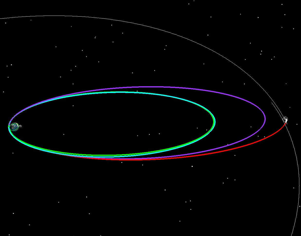
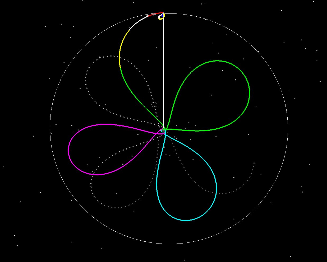
The final extended mission orbit for IBEX is shown in Figure 3 (another rotating view) which has an orbit period that is 1/3 of the Moon’s period. Note that the final orbit (in blue) has apogees that keep clear of the Moon.
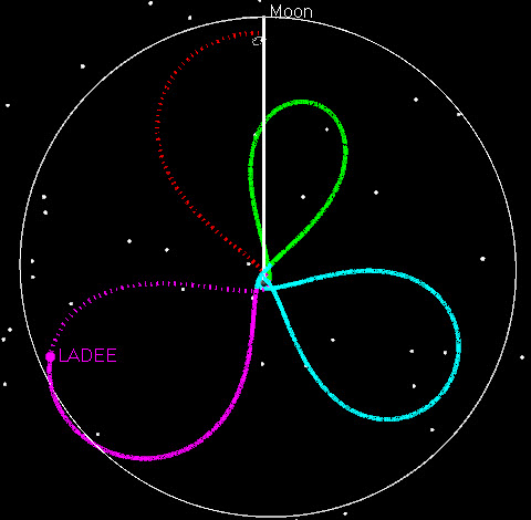
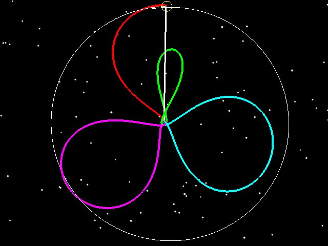
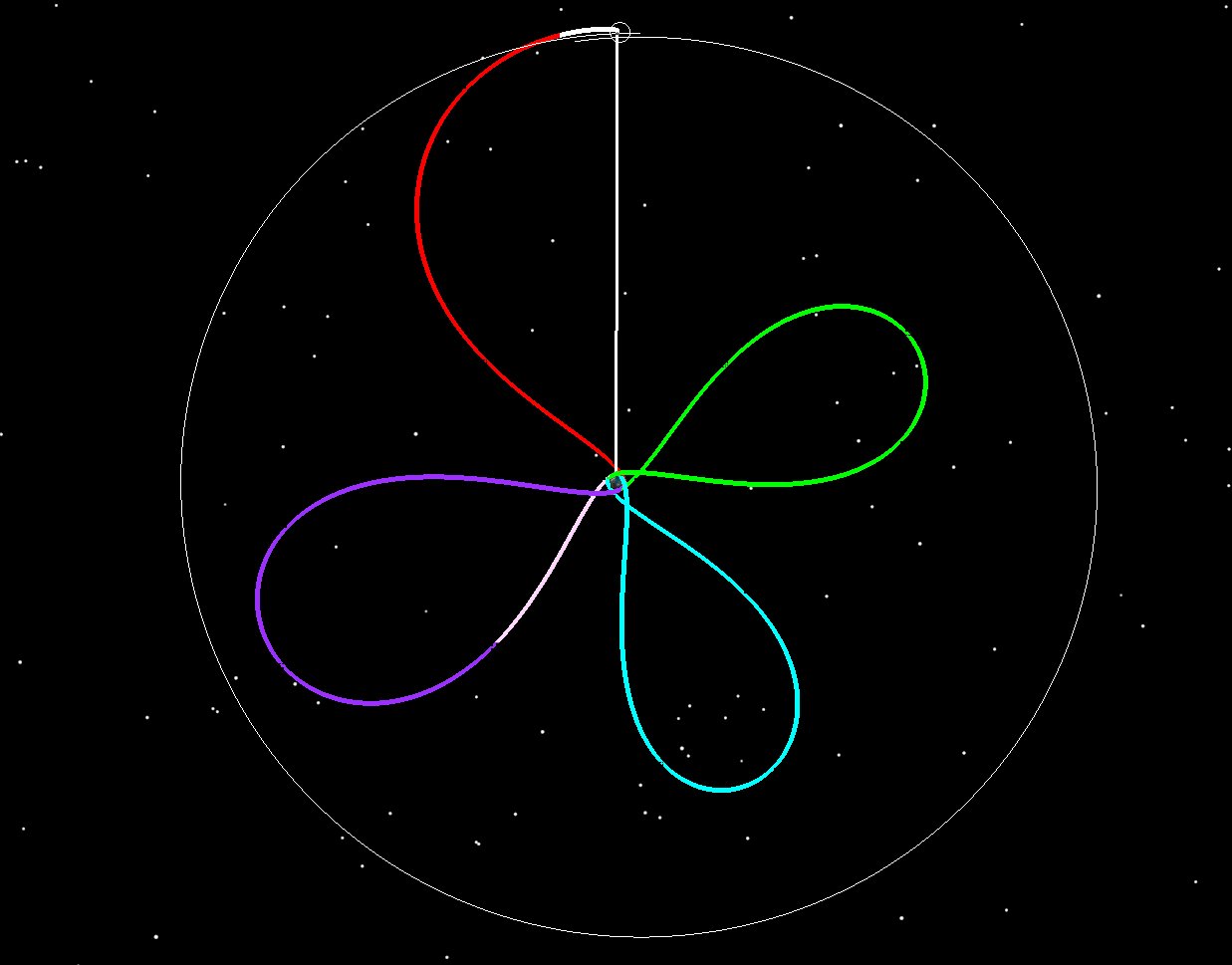
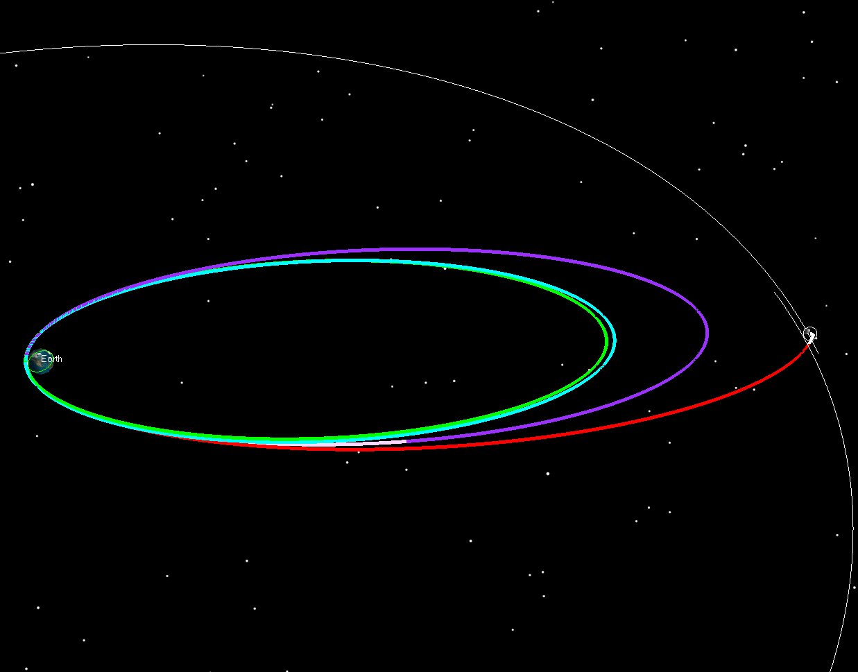
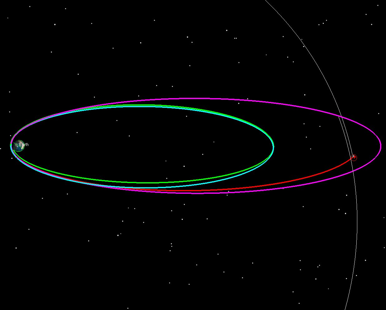
The Lunar Atmosphere and Dust Environment Explorer (LADEE) flew in 2013 and spent 6 months in lunar orbit. The cislunar portion of the mission consisted of 3.5 phasing loops, which extended the launch window and reduced the delta-v requirements of the mission. Figure 4 shows the Earth-Moon rotating view of the trajectory, while Figure 5 shows the inertial view. SEE worked closely with NASA Ames Flight Dynamics personnel to design the trajectory and then execute it in operations.
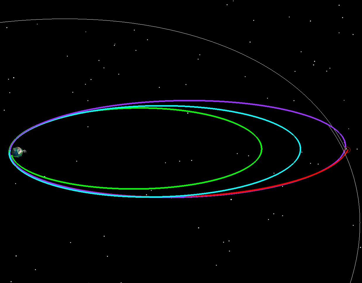
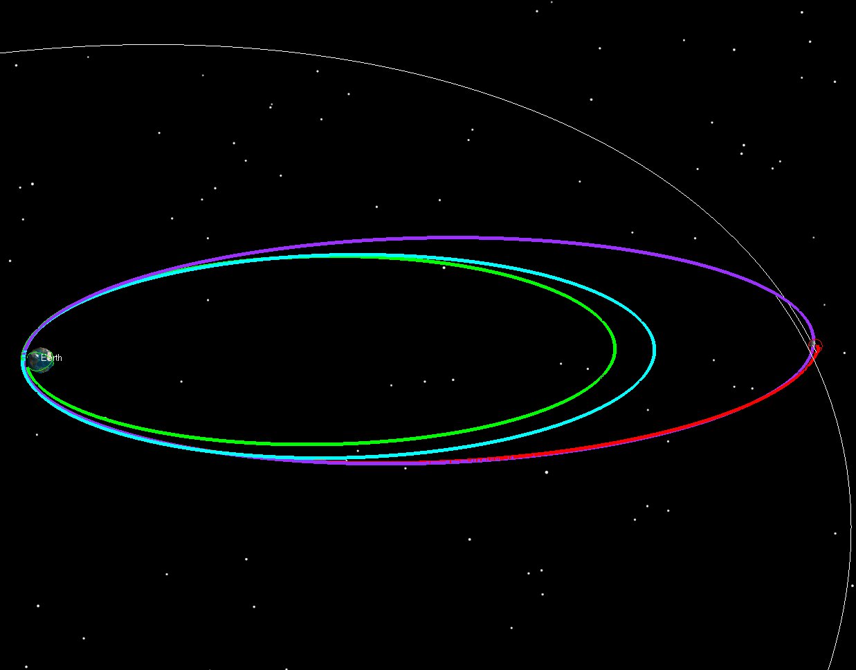
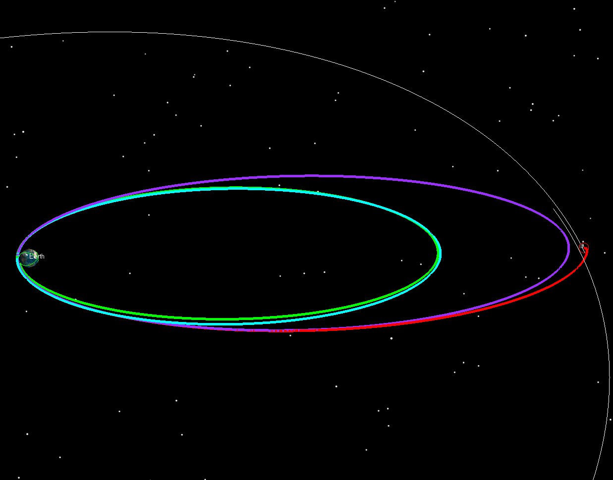
The Transiting Exoplanet Survey Satellite (TESS) launched in 2018 and used a combination of phasing loops (3.5) and a 2:1 resonant orbit, combining features of both IBEX and LADEE trajectories. SEE personnel worked with GSFC engineers to design and fly the mission. Figures 6 and 7 show the phasing loops once again.
In February of 2019, the SpaceIL “Beresheet” lander used a lower starting point with a super-GEO GTO with an apogee near 60,000 km altitude. A series of initial phasing orbits at lower altitudes then had been used on LADEE or IBEX) were necessary. SEE helped design the trajectory, trained the SpaceIL and Israel Aerospace Industries (IAI) Flight Dynamics engineers, and supported them during operations. Figures 8 and 9 show the cislunar portion of the Beresheet trajectory.
The CAPSTONE launch provides a different challenge, as the Electron rocket leaves the Photon + Capstone pair in a really low Earth orbit. We have to do a series of fairly big maneuvers to raise apogee, while giving ourselves enough time between burns to find out how the maneuvers performed, and plan the next one. All of this goes on while the perigee and RAAN are moving due to the Earth’s gravity field. Note that in Figure 10, the starting orbits are really small, compared to starting orbits we’ve used in previous missions.
Figure 11 shows the 7 levels that are used to get to the final targeted asymptote. Finally, Figure 12 shows the same trajectory in an Earth Inertial frame. While the figures don’t show it, there is typically 12 hours or more between each burn, and the entire sequence takes roughly 6 days after launch to achieve.
Once the CAPSTONE spacecraft is precisely placed on its target asymptote by the Photon stage, it is then on a Ballistic Lunar Transfer from which it will approach the Moon and enter into a Near Rectilinear Halo Orbit (NRHO). Figure 12 shows the Ballistic Lunar Transfer CAPSTONE uses to transit to the Moon in an Earth-Sun rotating frame. Finally, Figure 13 shows the same trajectory in an Earth Inertial frame. The BLT and NRHO portion of the mission were planned by our friends at Advanced Space in Colorado. Please visit their page for extensive details of the CAPSTONE Mission:
Mike Loucks and I were at agi.com last week in their new studio and we recorded this video blog on YouTube with Josh Poley. We’re talking about some Lunar missions we worked on:
Not sure why this never got posted, but I meant to put this link up 3 years ago during the middle of LADEE OPS. I created a draft version of the post, and then lost track of it.
Anyway, here’s a great article written by Liz Fuller-Wright, an excellent writer from the CSM who interviewed John and me about LADEE during the midst of the phasing loops.
A “Star Wars” Rebel astrogation Officer does some “back of the envelope” work
As I was watching the great success of the New Horizons team, I became motivated to do a bit of quick “back of the envelope” calculations to re-create the trajectory. I don’t have to start completely from scratch, because in 2004 I created an STK/Astrogator tutorial giving the basic ideas of how to set up the New Horizons trajectory:
I thought it would be fun to update things and make them closer to what was actually flown. I can easily do so because the New Horizons Astrogator Yanping Guo (along with legendary Astrogator Bob Farquhar) gave me what I need in this paper:
I will refer to this from now on as “Yanping’s paper” just for simplicity, but Farquhar helped write it as well.
I’m going to do this in STK/Astrogator, but the basic idea would be similar in other software. I’ll update my scenario a bit to include the launch portion along with the published B-plane parameters at from Yanping and see if our geometry lines up with hers. (STK/Astrogator was actually used for the New Horizons mission, which makes this even more relevant. It was also used on Messenger, LRO, LCROSS, LADEE, etc… but I digress.)
Launch Targeting
Firstly, let’s get the launch set up, so that I can hit the right time of the launch coming out of KSC. The Launch vehicle used was an Atlas 551, a beast of an Atlas with 5 solid boosters, a Centaur upper stage, a Star 48B on top and the 5 meter fairing. That’s actually one heck of a stack of stages. Here’s a really cool report of the launch events, according to Jonathan McDowell:
“The powerful Atlas 551 rocket, with five solid boosters, roared off the Florida pad after two days of delays. The solids separated at 1 min 45s into launch, arcing into the mesosphere before falling to Earth. The 5-meter-diameter fairing separated at 3min 23s, followed seconds afterwards by the two pieces of the CFLR (Centaur Forward Load Reactor), a contraption that connects the smaller 3.1m-diameter Centaur to the fairing for structural stiffness. By this time Atlas was in space, with the fairing probably reaching an apogee of 150 km or so. Atlas shut down at 4min 27s, falling away 6s later, and the Centaur second stage ignited at 4min 33s as the trajectory flattened out, reaching orbit insertion at 1910:08 UTC with a 167 x 213 km parking orbit. The vehicle coasted for 20 minutes and restarted over South Africa, with a 9-min burn taking the Centaur to 800 km altitude at a velocity of 12.4 km/s, a hyperbolic Earth orbit which will take the Centaur out to the asteroid belt. At 1939 UTC the spin-table on the forward end of the Centaur began to rotate, and the injection stage with the payload separated. The injection stage is an Alliant (Thiokol) Star 48B solid motor, the same motor used on Delta 2 third stages and on the old Shuttle PAM-D flights. Solid kick motors like to be spinning when they fire to even out any misalignment of the thrust direction, hence the spin table – although the Star 48B also has a set of small hydrazine rockets to correct any unwanted nutation. After the Star 48B burn, the payload had reached escape velocity not only with respect to the Earth but also relative to the Sun (The velocity was 16.2 km/s relative to the Earth and I estimate an asymptotic velocity of 12.3 km/s, corresponding to 42.6 km/s relative to the Sun and leading to a heliocentric eccentricity of around 1.05)”
(You should follow Jonathan on twitter: @planet4589 and you can find the latest version of his “Jonathan’s Space Report” here: Jonathan’s Space Report)
I have to divert a bit from my deep space trajectory because I’m geeking out about the Atlas 551. That’s a sweet rocket. Let’s see a picture of the stack from the launch press kit:
New Horizons Atlas 551 Launch Stack (From NH Launch Press Kit) Click to Enlarge
Ok, let’s just look at rocket itself. (You really want to click on this one, it’s a cool rocket!)
New Horizons Atlas 551 (5 meter fairing, 5 solids, 1 RL10 on the Centaur) [Click to enlarge]
The Star 48B is a very reliable (and available) upper stage, and stacking it on top of a Centaur is pretty unusual, but necessary for the high C3 (157.64 km^2/sec^2). That C3 is (as noted by Jonathan) hyperbolic with respect to the Sun!
Let’s take a quick look at the staging profile (also from the press kit):
Launch Events (1 of 2) [Click to Enlarge)
Launch Events (2 of 2) [Click to Enlarge)
Our purpose here is to duplicate the interplanetary trajectory, so I’m not compelled to completely duplicate the launch segment. I’m going to model all burns as impulsive burns (I don’t have their engine models anyway) and I’m going to combine the Centaur and Star 48B into one insertion burn. It’s fine to do this, since ultimately the multiple insertion burns are just targeting a single trajectory after launch, with a single defined asymptote. The Centaur and Star48 burns were optimized to hit a single asymptote, so I’ll just model that part.
From my NH tutorial mentioned earlier, I will re-use these asymptote conditions:
2006 New Horizons Asymptote (from Trajopt)
These conditions came originally from Trajopt (an old DOS program written at SAIC) and they’ll be good enough. I could have gotten them from a variety of other sources that help you search for planetary swingby opportunities. I’ve used MAnE, Trajopt and “Swingby Calculator”, and there are many others. Regardless, these conditions are plenty good and they ought to get me to the Jupiter swingby, and then I’ll work from there.
So I will launch out of KSC with these conditions:
Astrogator Launch Burnout Conditions
In STK/Astrogator, we model the launch as a portion of an ellipse that starts at the ground and then meets the launch insertion state. This is a decent estimate of the burnout state. After the launch, we’ll coast in orbit for a bit, and then execute an escape maneuver. The mission control sequence for that looks like this:
STK/Astrogator Single Targeter to hit outgoing Asymptote
So I’ll vary my launch time (to get the orbital plane, or the Right Ascension of the asymptote) , my coast duration before the impulsive escape delta-v (to get the Declination of the asymptote) and the delta-v itself (to get the C3, or energy) to hit the asymptote conditions. When I do that, I get this type of a flyby at Jupiter:
New Horizons Trajectory with Asymptote only.
So using the Trajopt asymptote does actually create an encounter with Jupiter, but I don’t get anywhere near Pluto. According to Yanping’s paper, my flyby should look like this:
New Horizons Jupiter Flyby (from Yanping’s paper sited earlier) [Click to Enlarge]
But if you go into the Jovian system for my flyby, you’ll see this:
Asymptote only targeting, Jupiter flyby side view
Asymptote only targeting, Jupiter flyby side view
So that tells me that the asymptote isn’t going where I want. I can fix that pretty easily. Yanping gives me the B-plane parameters I need at Jupiter to continue on the Pluto. If I match these parameters, I should then be close enough to an encounter with Pluto that Astrogator can target me the rest of the way in. I’ll match them by slightly varying my departure asymptote parameters.
The B-plane is a fictional plane that is used for precise targeting during a gravity assist or for planetary orbit insertion. It can be best thought of as a bulls-eye or target plane attached to the assisting body. The trajectory’s intersection point on the B-plane is where the spacecraft would go if the swingby planet had no gravity. This turns out to be useful because B-plane targets behave very linearly as you move the trajectory around (while targeting) while the actual periapsis point (or closest approach point) doesn’t move very linearly near the planet due to the non-linear force of gravity.
The B-plane is defined to be the plane that contains the focus (usually the center of mass of the body) of an idealized two-body trajectory (assumed to be a hyperbola) that is perpendicular to the incoming asymptote of that hyperbola. The incoming and outgoing asymptotes, S and O, and the focus of the hyperbola are contained in the trajectory plane, which is perpendicular to the B-plane. The intersection of the B-plane and the trajectory plane defines a line in space. The B-vector is defined to lie along this line, starting on the focus and ending at the spot where the incoming asymptote pierces the B-plane. A reference vector (R) is used to externally define the other planar axis. There are different choices to use for R. Typical examples are the planet’s orbit normal, or the planetary pole vector. You can use whatever you want, as long as you specify what it is (so others can duplicate what you’re doing, like I’m about to do)
Bplane Definition
The vectors T and R lie in the B-Plane and are used as axes. The coordinates of our point in the coordinate system defined by those axes are called BdotT and BdotR, and they are the standard parameters given that allow you to target a swingby.
My initial state from Trajopt gives me the right direction for my transfer trajectory to get close to our B-plane targets (i.e. somewhere in the Jovian system), but I’m going to substitute in the B-plane parameters from Yanping’s paper instead of those that Trajopt originally generated. This should get me close enough to Pluto to hit our B-plane targets later.
I will target the following at Jupiter (From Yanping):
B-Plane Target: B dot T = 342421 km B dot R = 2629560 km Jupiter Periapsis (closest approach) time = 28 Feb 2007 12:00:00.000 UTC
(Jupiter’s North Pole Reference frame)
I’ll use these parameters for now, and then let them be varied later. On the real mission, Yanping used trajectory correction maneuvers (planned for up to 25!), and didn’t try to accurately hit the Pluto B-plane precisely all the way back from launch. I can get away with that here, so I will. If I wanted to simulate how a real mission would do it, I’d truncate off my asymptote solution back at Earth, and our B-plane targets at Jupiter and recover from those errors with TCMs. In a numerical simulation, I can pretend that I can hit targets much more precisely than I can in real life, so I’m going to cheat here and do that.
I will use a double-nested targeter to achieve our goals. The inner targeter varies the Launch Time, the Coast duration, and the Injection delta-v to achieve the asymptote conditions. The outer targeter will vary the asymptote conditions of the inner targeter (RA, Dec and C3 of outgoing asymptote), in order to achieve the desired B-plane parameters and arrival epoch at Jupiter. So I’m going to let the targeter vary my first guess at the outgoing asymptote from Earth (the guess that came from Trajopt) in order to hit the B-plane parameters that Yanping says I need. The Astrogator MCS for this is below:
STK/Astrogator Mission Control Sequence with Double Nested Targeters
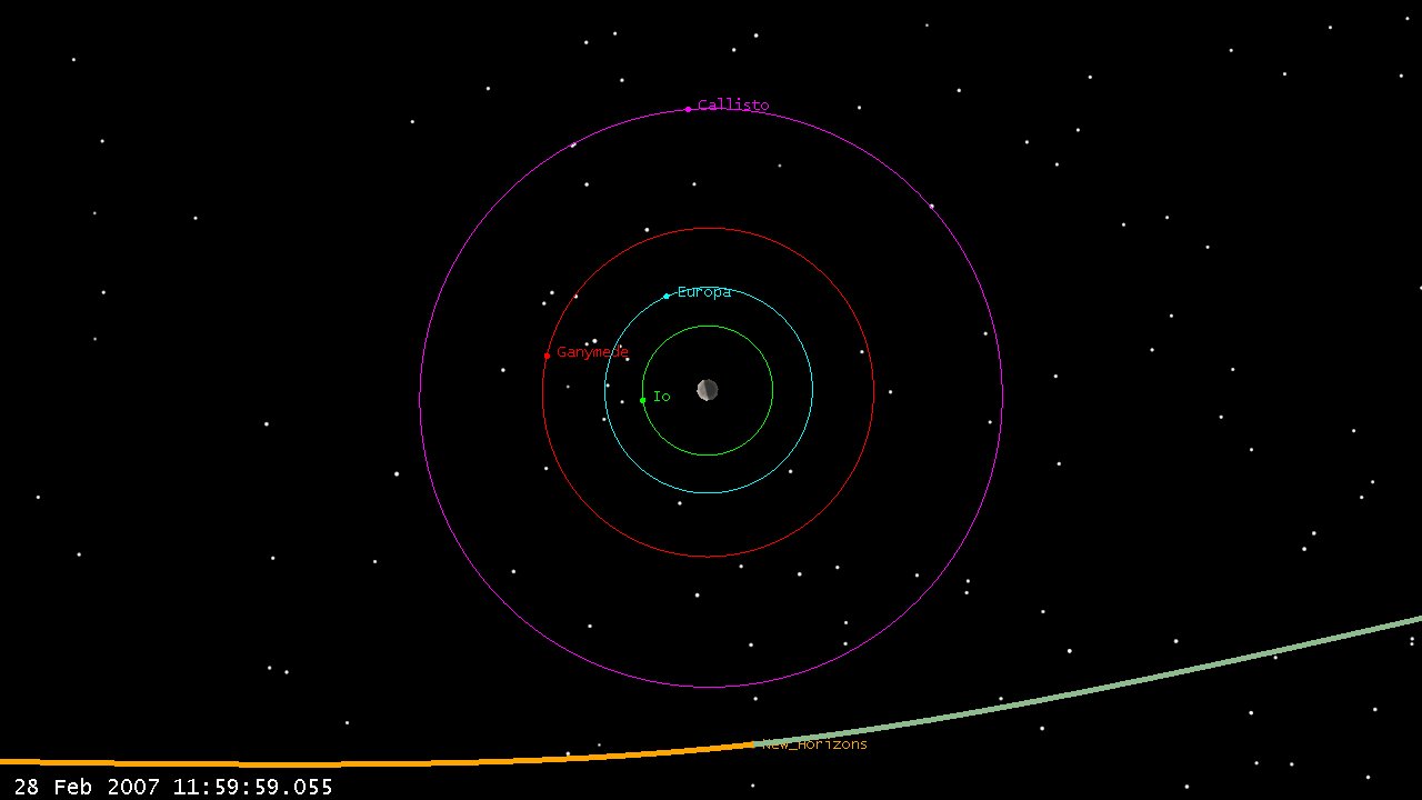
After this converges, my trajectory looks like this (view at Pluto closest approach):
New Horizons Trajectory with Jupiter Bplane Targeting [Click to Enlarge]
Which is a lot closer. The Pluto arrival date isn’t exactly right and while it looks close on the solar system scale, I am actually 5.9 million km from Pluto at periapsis. This shouldn’t surprise me though, because I haven’t really targeted anything at Pluto yet. I am relying solely on the Jupiter B-plane parameters to get us there. At the Jupiter flyby, my geometry looks like this:
Bplane Targeting (double nested), Jupiter flyby top view [Click to Enlarge)
Which looks a lot more like the encounter geometry that Yanping showed in her paper. So now, I’d like to actually target my Pluto periapsis to the right spot and at the right time to match the encounter.
Again, I’ll rely on Yanping’s paper to tell me what I want to hit:
B-Plane Targets: B dot T = -10910.6 km B dot R = 2041.9 km
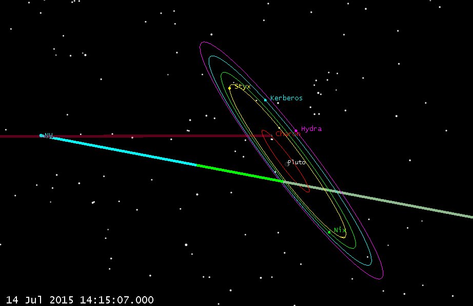
Pluto Periapsis (closest approach) time = 14 Jul 2015 11:58:59 UTC
(Pluto orbit normal frame)
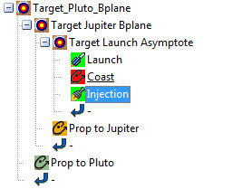
I will target this with a triple nested targeter (highly bogus in terms of trajectory realness in this case, but cool anyway). It looks like this:
Triple Nested Targeter: Hitting the Pluto B-plane all the way from Insertion
1. The deepest internal targeter (Target Launch Asymptote) varies the launch time, coast duration, and burn delta-v to hit the outgoing asymptote (RA, Dec and C3 of asymptote)
2. The second targeter (Target Jupiter Bplane) varies the outgoing asymptote conditions of the deepest targeter in order to hit B-plane parameters at the Jupiter swingby.
3. The outermost targeter (Target Pluto Bplane) varies the B-plane parameters at the Jupiter Swingby in order to hit the desired B-plane parameters at Pluto.
This setup is simple but powerful and gets an answer, but I couldn’t really do this when flying a mission. It essentially has me targeting the Pluto B-plane accurately from conditions all the way back at insertion in Earth orbit! Launch vehicles can’t hit the asymptote RA and Dec within 0.000001 degrees, nor can injection maneuvers be executed with precision of 10e-6 meters. I’m going to ignore that though, since I know I’d have to do midcourses, and just enjoy the coolness of the trajectory.
So in my uber-precise mathematical universe we get this at arrival:
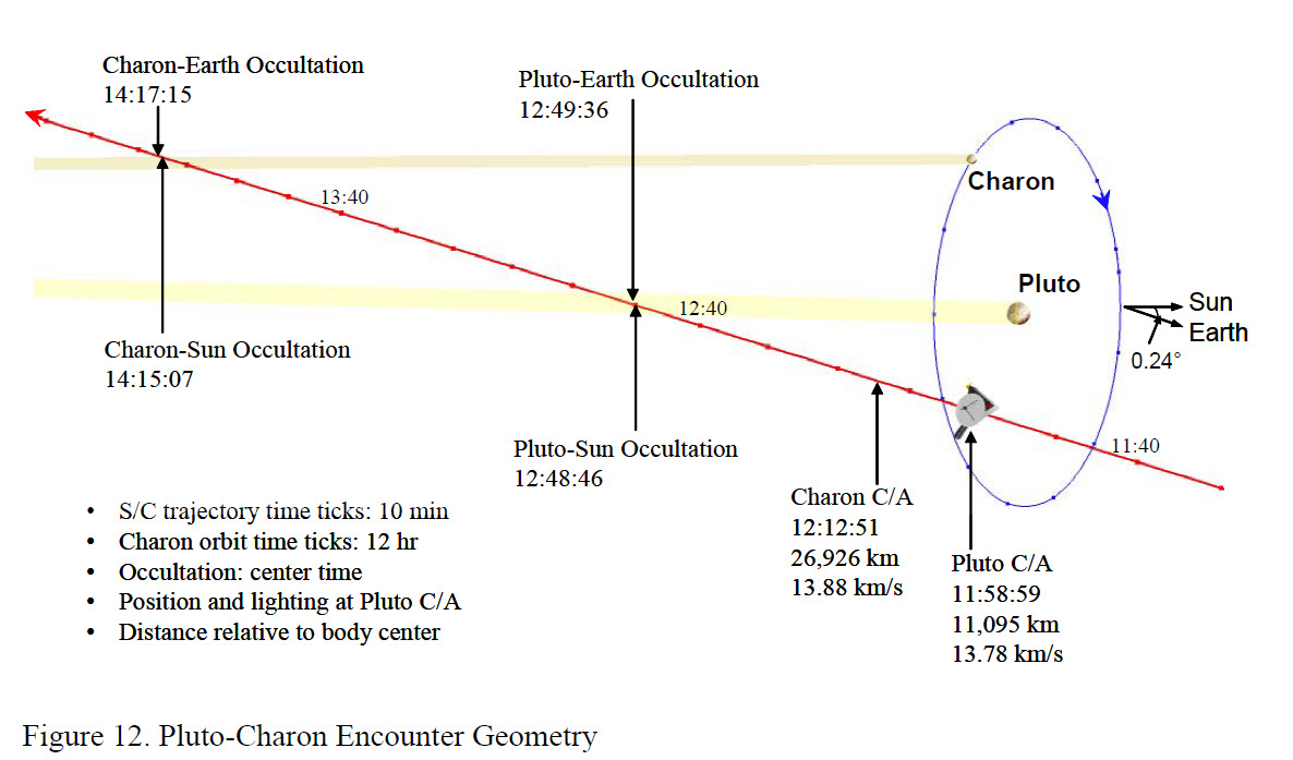
Pluto Periapsis Geometry
From Yanping’s paper she has the geometry looking like this:
Pluto Approach Geometry (Gua and Farquhar)
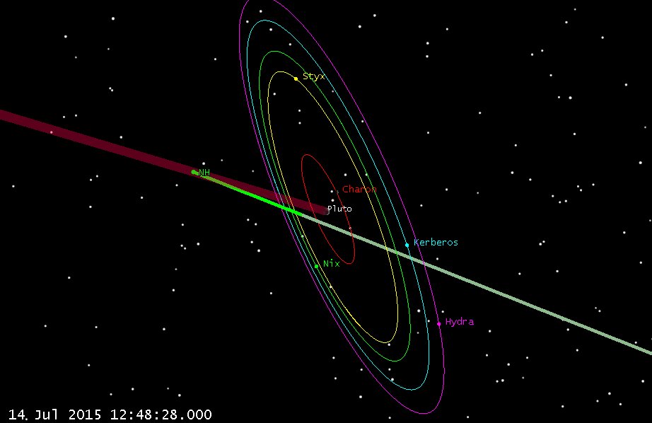
We can also look at both sun occultations to see if they match up:
Pluto Occultation of Sun
Charon Occultation of Sun
And they do (which is pretty satisfying!) Of course our fellow Astrogator Yanping Guo had to do things much differently than this, since she had to correct out insertion errors, attitude dumps, and Orbit Determination (OD) errors, etc. all along the trajectory for 9.5 years! In fact while they had planned 25 Trajectory Correction Maneuvers (TCMs), they only had to perform 9, which saved them 2/3 of the planned delta-v. This gives them plenty of delta-v to use to retarget to a Kuiper belt object later this year (pending additional NASA funding). Once they announce the target KBO object, I’ll update and extend my trajectory to match.
Also, I think the final conditions at the encounter may have been slightly off from what I have here (due to TCMs, adjustments, etc. that occurred after the paper was written). Once I get my hands on those conditions, I can trivially re-target things to achieve those states instead of what I hit above. (and I will, and will update here). What I’ve found so far has been conflicting, so I’ll stick with the paper. If someone has better data, pass it on. It’s easy to re-do.
I end this fun with a bit of animation showing the Plutonian system in action. I’d been wanting to see an animation of the system with the dual-planets co-orbiting, so I just made one myself. I love seeing Pluto dancing around the system barycenter. Planet and moon positions come from JPL SPICE files.
On CNN.com there was a story “Meteorite makes big crater in Nicaragua” by Amanda Barnett. In the article, Amanda wrote: ‘AP quoted government spokeswoman Rosario Murillo as saying they’ve determined it was a “relatively small” meteorite that “appears to have come off an asteroid that was passing close to Earth.”‘ Well, that’s enough to get someone wondering if indeed it could have come off 2014 RC, which just did the flyby this past Sunday, 7 Sep 2014 at 18:15 UTC.
Well, Adam Gorski at Analytical Graphics made this easy by posting an STK scenario on AGI’s website blog: Asteroid 2014 RC flyby on Sunday. Adam got 2014 RC’s ephemeris from the JPL Horizons website, and set everything up. THANK YOU ADAM!
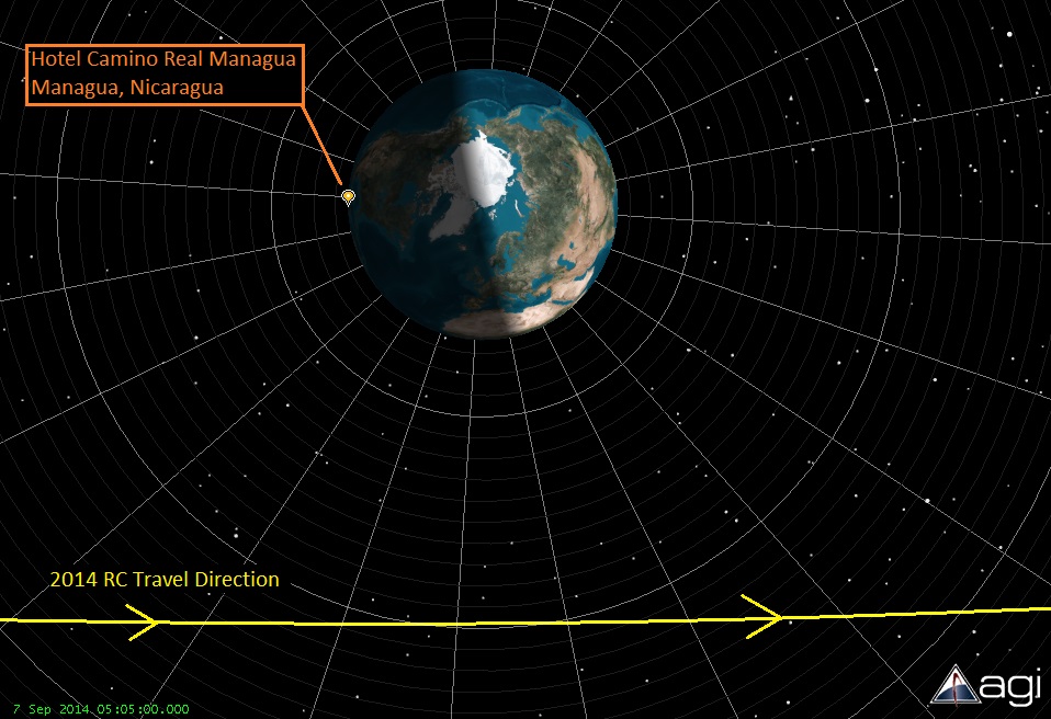
In Amanda’s article, she says “The Nicaragua Dispatch said the hole is in the woods near Managua’s Sandino International Airport and about 1,000 feet (300 meters) from the Camino Real Hotel” which, according to Google Maps is at Latitude 12.148060, Longitude -86.184949. So, I put this into STK as a place object.
Amanda also mentions the time of impact, which is critical to this: “The Today Nicaragua site reported the crater was found after a loud blast about 11:05 p.m. on Saturday. ” Nicaragua is in the Central Time Zone, and from a few web searches seems that they do not use daylight savings time. So the time should be UTC – 6 hours. So, 11:05 pm on Saturday would be 7 Sep 2014 05:05 UTC.
So, with the location and the time, we can see if the Hotel was on the side of the Earth from which the asteroid was coming from:
So, that seems pretty obvious. (Even if the time is off by an hour or so, it’s still on the correct side of Earth.) In this STK view, asteroid 2014 RC is traveling from left-to-right, and the hotel near which the crater was found is on the same side of the Earth. So far this myth is NOT busted; it’s plausible.
So the direction seems reasonable, but we want to see if it’s reasonable that this meteorite could have come off of asteroid 2014 RC. We can use a similar approach that several us did a few years ago investigating a potential space debris collision, as written in the paper “INVESTIGATING ORBITAL DEBRIS EVENTS USING NUMERICAL METHODS WITH FULL FORCE MODEL ORBIT PROPAGATION.” (by Timothy Carrico, John Carrico, Lisa Policastri, Mike Loucks, AAS 08-126.) We can see if a reasonable force applied in the past could have knocked a rock off of 2014 RC, or perhaps another impact caused a chunk to be thrown off.
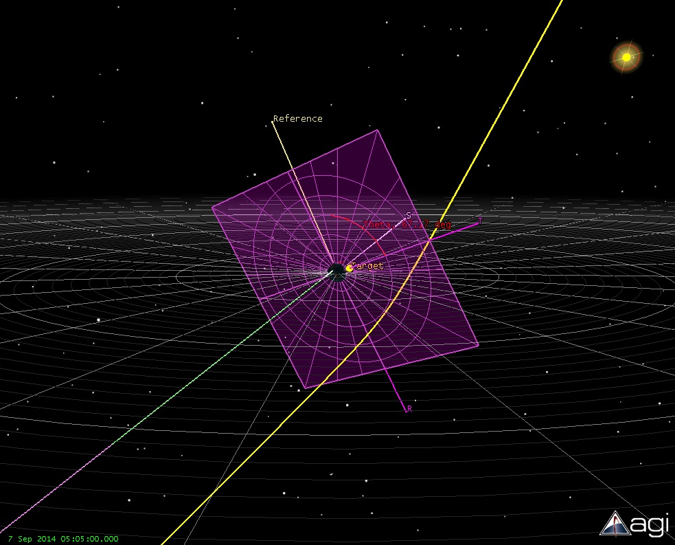
We can model this in STK/Astrogator by getting an initial state for 2014 RC in the past, and calculate what delta-V (change in velocity) would be needed to divert from 2014 RC’s trajectory to hit near the hotel at the observed time. Not knowing when the meteorite could have left its host, I chose to investigate the case if the rock left the asteroid 10 years ago. So, using our favorite “Follow Segment” in Astrogator, I propagated the initial state of the Asteroid that Adam had found backwards in time for ten years. Then I modeled a small impulsive delta-V, and set up the Astrogator targeter to calculate the delta-V needed to hit the hotel at the specific time. I set up the targeter to hit Earth B-Plane values of B dot T = 0.0, and B dot R = 0.0 (hitting the Earth right in the middle, as seen from the approaching asteroid). And when that profile converged, the next targeting profile targeted the exact latitude and longitude of the hotel.
The B-Plane at the Earth as defined by the incoming meteorite trajectory.
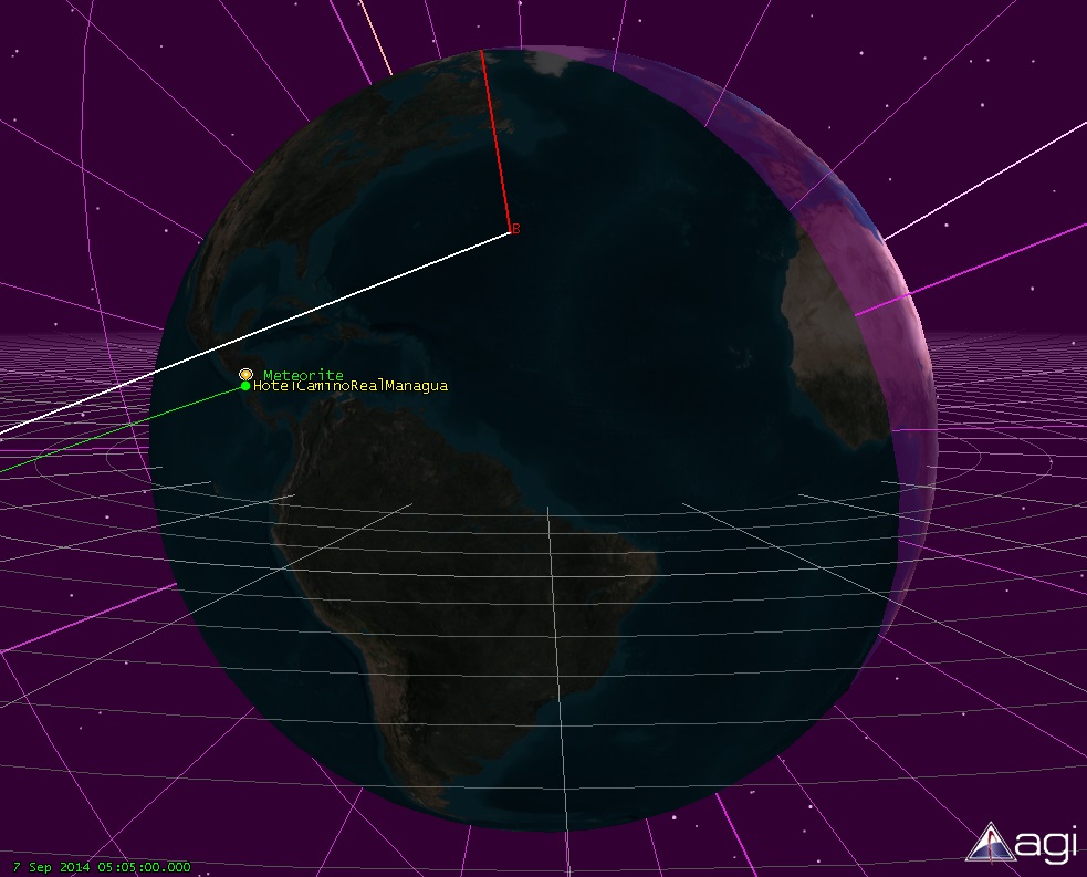
This converged pretty quickly, and gave a delta-V number of about 90 meters/second. Since an impact velocity of an asteroid could be 10 or more km/second, this low value seemed very reasonable. And, if the rock had come off a hundred, or several thousand years ago, it would take even less delta-V to hit near the hotel. So, once again, the myth is NOT busted, and it’s very plausible that this meteorite came off of asteroid 2014 RC as some point in the past.
Close up view of the meteorite trajector impacting near the hotel
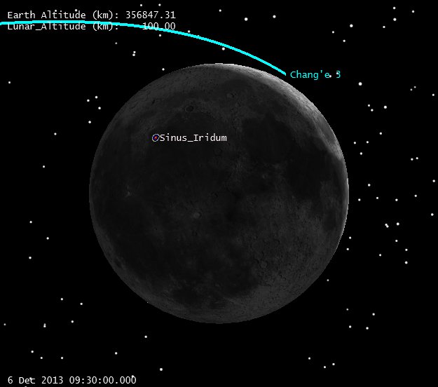
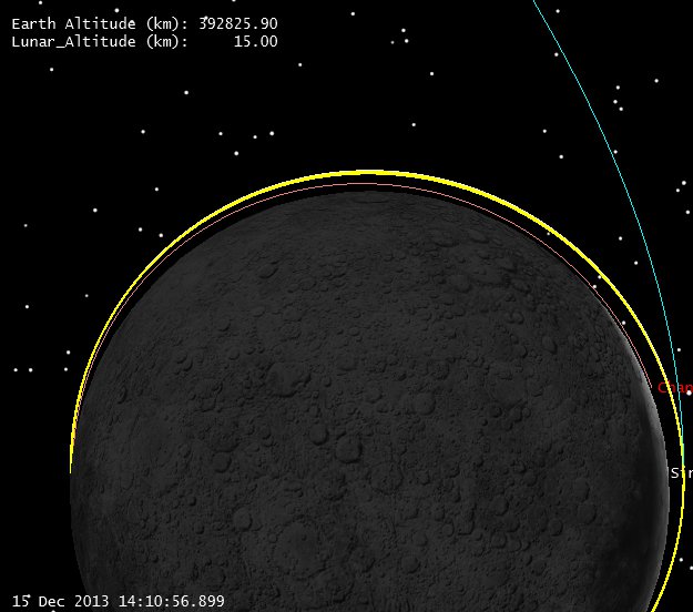
The Chang’e 3 Lander is on the surface! What an amazing accomplishment for our Chinese friends. Now that it’s down, let’s take a look back at our guesses of the trajectory and see what we got wrong, and what we know about the real trajectory now that we know the landing site and the time of the landing.
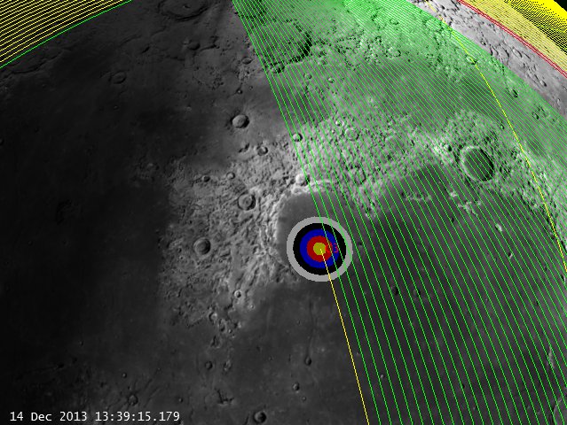
First off, note the real landing site, compared to the landing site that was identified pre-launch
Real landing site/time Lat = 44.12 deg N. Lon = -19.51 W @ 13:11:18 UTC.
Reported site/time Lat = 43.07 deg N. Lon = – 31.05W @ 13:40 UTC
Real landing site with the bullseye to the east, prelaunch reported site to the west.
Real vs. Reported Landing Site (click to zoom)
So what does this tell us?
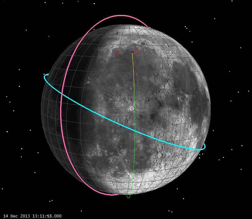
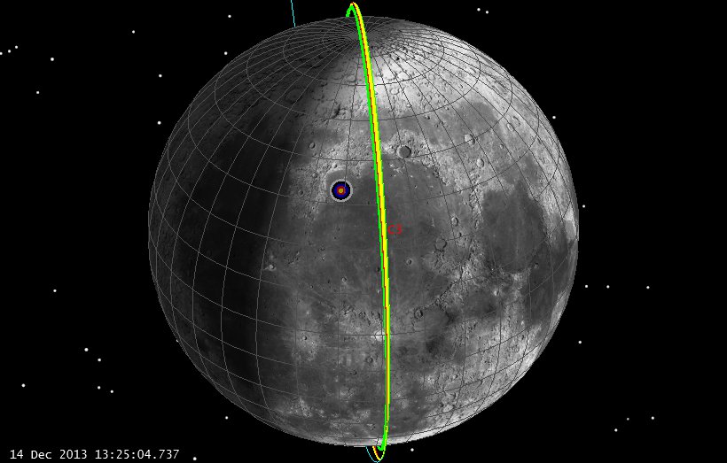
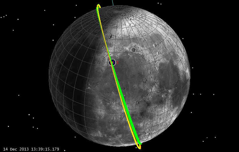
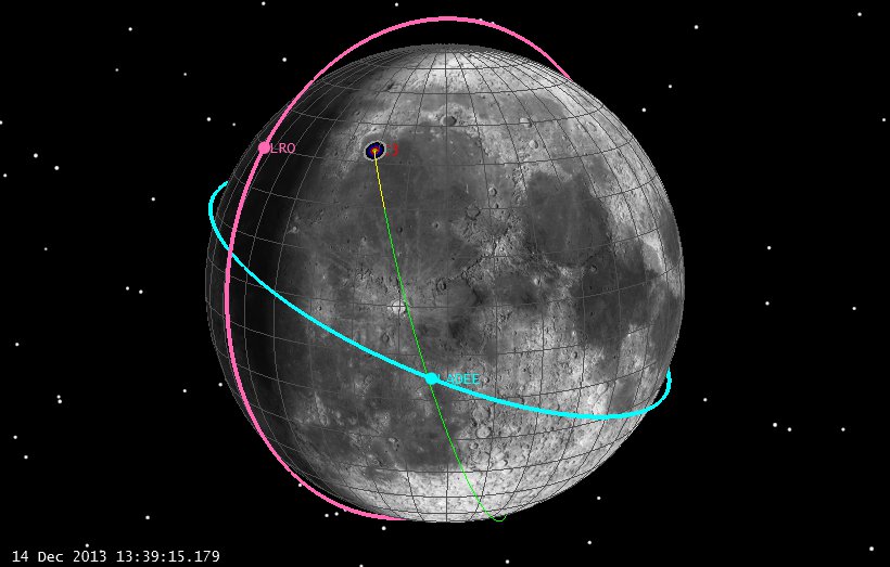
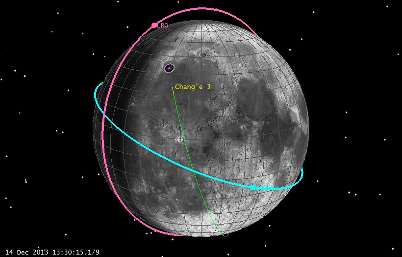
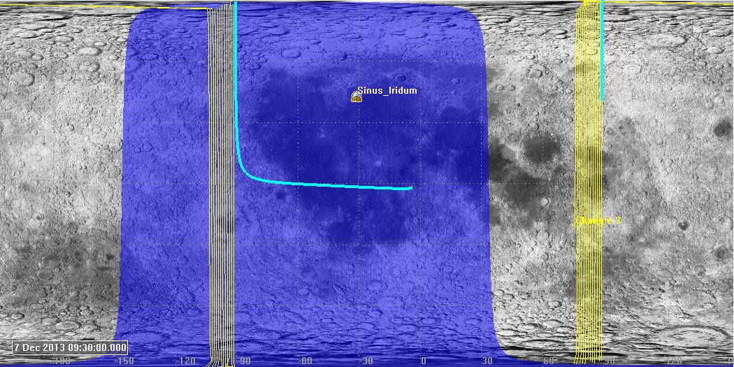
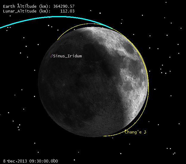
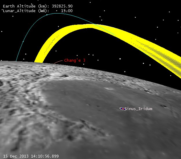
As we suggested in our earlier posts, the reported landing site could not be achieved at the landing time from a 90 deg inclination orbit. The actual landing site, however, could be (and was) achieved from 90 degrees. Let’s check out then, what it must have been (LRO orbit in magenta, LADEE orbit in Blue, neither on the same side during the landing):
Real Landing Geometry of Chang’e 3 (click to zoom)
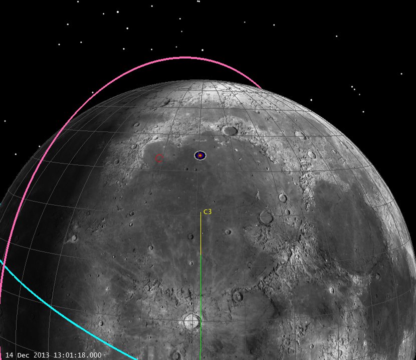
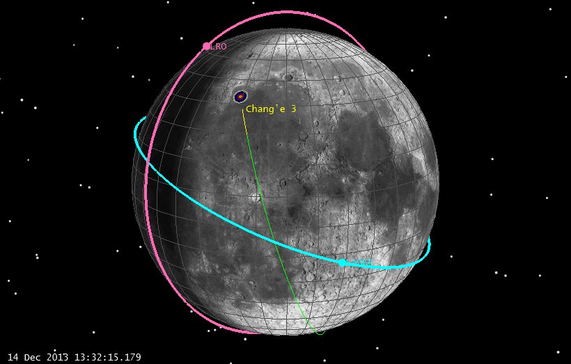
And ten minutes before:
Real Landing Geometry of Chang’e 3, L-10 min (click to zoom)
So we didn’t need a different inclination, 90 degrees was fine. With the proper landing time and site, we would have had a really good estimate of the trajectory. It’s all “basic geometry, and we know about that!”
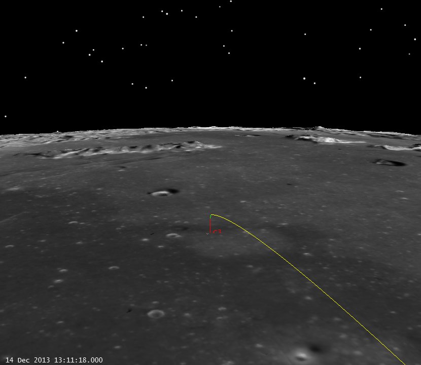
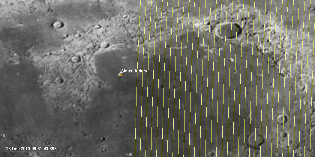
Finally, here’s the local terrain looking from the southwest.
Chang’e 3 Landing Site, (click to zoom)
Again, really cool work by the Chinese Chang’e 3 Team!
With our last post, we identified the overall nature of the Chang’e 3 trajectory, now let’s try to narrow it down a bit to see what the landing approach might look like.
Firstly, we should add to the previous post. You might have noticed in the last posting:
Chang’e 3 LOI Geometry (Click to zoom)
We show here a lunar arrival from the North. That’s not the only available approach. We could also approach from the south and get the same inclination:
Chang’e 3 North and South LOI approach (click to zoom)
Which gives us two possible approaches to the landing site. Our current information has the spacecraft approaching the site from the south, so we can switch things to accommodate that.
Our Chinese friends announced that they did achieve LOI at 6 Dec 2013 09:53. This time represents the conclusion of a 361 second burn, which places the center of the burn at 9:50. That’s where we can put our impulsive LOI maneuver.
Once there, we’ve been told C-3 circularized in a 100 x 100 km (altitude) orbit.
From there we are told (from Robert Christy @Zarya_info):
1. The periselene was dropped to 15 km on Dec 10 13:20 UTC
2. The periselene will be further dropped to 2 km on the orbit before landing.
3. Landing will take place in Sinus Iridum with coordinates 43.07 deg N Lunar Latitude, 31.05 deg W Lunar Longitude.
5. Landing will take place Dec 14 13:40 UTC with the landing start at 13:26 UTC from periselene
Can we deduce the landing profile, and thus the inclination from this? Perhaps.
Note that all press so far has referred to this orbit as merely “polar”. While we might assume this means exactly 90 degrees, I don’t think it can be 90 if we stick with the landing site and landing times we list above. See below that if we assume a 90 degree inclination, we can’t get to the appointed landing site at the appointed time (bullseye represents identified landing zone):
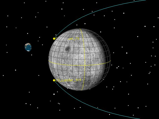
90 deg inclination Moon Fixed orbit track (click to zoom)
Note the time in the lower left. Lowering and raising the orbit won’t help, the Moon simply hasn’t rotated under our orbit plane at the landing time. How confident are we of the orbit plane? Pretty confident. The cislunar transfer is relatively fixed. We know the launch time, launch site, perigee location and the transfer time to LOI. We know (roughly) the capture aposelene altitude, so we’re only left with inclination to play with. Could there be a plane change somewhere after LOI? Sure, but this seems like a pretty unlikely fuel cost, especially when we can just get what we want by changing our inclination. Another way of looking at this is to check it out in inertial space:
90 deg inclination Moon Inertial orbit track (click to zoom)
This makes things a bit more clear. Our orbit plane is pretty inertial (note the orbit plane is pretty fixed over a week of time in orbit since LOI). We just have to wait for the Moon to rotate underneath. If we land on the 14th at 13:40, our site just isn’t there yet. However, if we change our inclination to about 105 degrees:
104.7 deg inclination Moon Fixed orbit track (click to zoom)
Again with the inertial view:
104.7 deg inclination Moon Inertial orbit track (click to zoom)
We can see that a bit of inclination gives us just what we need, a relatively “polar” orbit, a ground track over the site, and a landing time that’s about right.
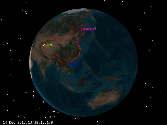
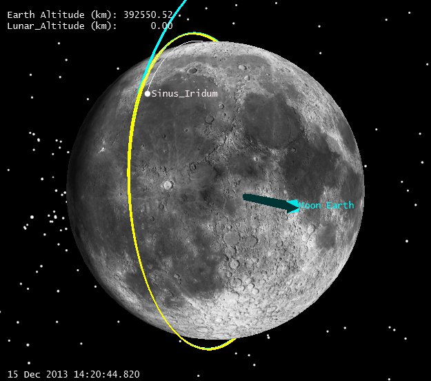
Let’s look again at what’s the view of Earth during landing:
Moon view of Earth at Landing (click to zoom)
Pretty good geometry, all 3 major Chinese ground stations well above the horizon for many hours.
So what are the sources of errors here? Many. We certainly don’t match the AOS and LOS times published. Those can easily be explained by the fact that we don’t know the actual parking orbit dimensions. We’ve been assuming 100 x 100 km circular (and we’ve played with that a bit to make things be timed right) but we’ve got 50+ revs in orbit for errors to build up, and we this assumes a perfect insertion at 100 km periselene, and a perfect insertion. We also don’t know precisely what altitudes were reached with our periselene lowering maneuvers, nor where the first periselene lowering maneuver was targeted (15 km at first periselene after the burn, or 15 km 20 revs later?) So we’ve got a lot of slop. Still, let’s assume that our landing time and landing site are right, and let’s see where a couple of our US satellites are that we know pretty well.
[Disclaimer: While I (Astrogator_Mike) was the trajectory lead during the cislunar phases of LADEE, I am currently only very very part time on the mission as off-site support during science ops, and right now -at this very minute- I am blogging on my spare time on SEE company computers. The trajectory information I am using for both LADEE and LRO is readily available on the JPL Horizons site and comes from there. Thus, no NASA funds, computers, data or assets of any kind were used in the making of this blog posting and I am doing this in my spare time.]
So, where are LRO and LADEE? Based on spice files from the wonderful aforementioned JPL Horizons site, here are where our US orbiting robots are during the Chang’e 3 landing:
LADEE and LRO geometry at landing (Click to Zoom)
So let’s step through this a bit close to landing and see what our geometry is.
L -10 (click to zoom)
L -8 (click to zoom)
L -6 (click to zoo)
L -4 (click to zoom)
L -2 (click to zoom)
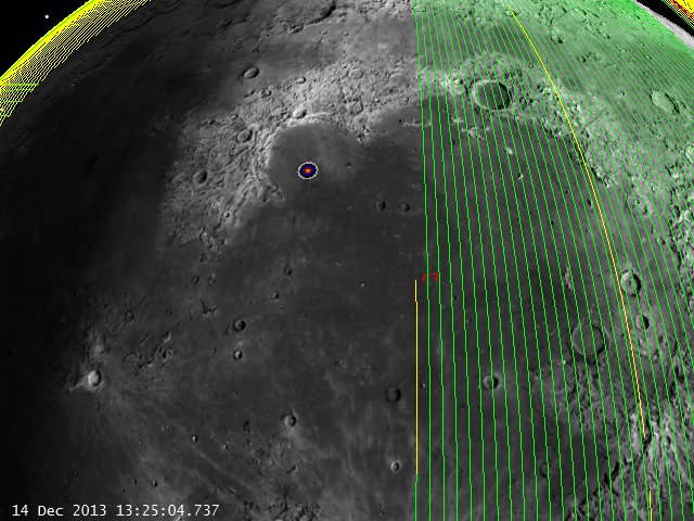
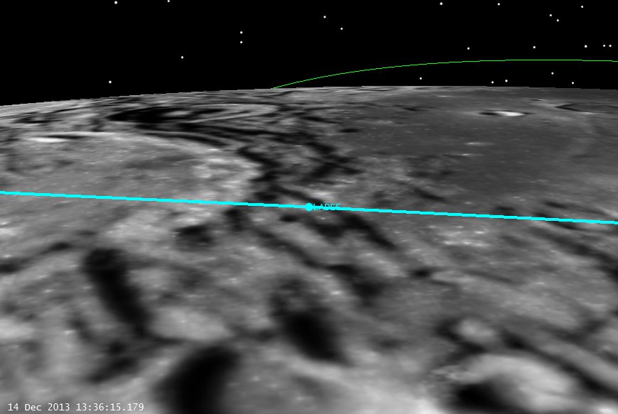
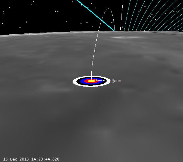
Let’s get a bit closer to the landing site, and see if LRO or LADEE can see the site:
C-3 Landing from LADEE (click to zoom)
Of course LADEE has no camera on board (except the star trackers) but it won’t be able to see anything anyway. LRO, on the other hand, has a decent horizon view of the landing and might be able to see something against the star field. So from LRO we have:
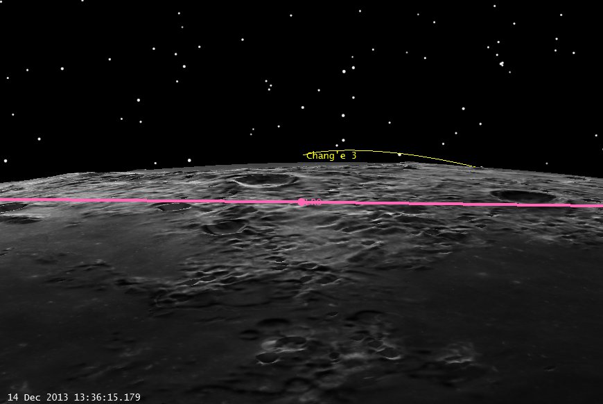
Landing from LRO (click to zoom)
Of course this all assumes that the times we have are right, but if LRO could somehow scan the area over the landing site during the right pass, they might be able to see something.
Regardless, good luck and godspeed to the Chang’e 3 controllers!
Our Chinese colleagues launched a lander to the Moon on December first, but unfortunately they have chosen not to publicly share where their spacecraft is. A few days ago there were several TLEs in Spacetrack associated with the Chang’e 3 launch, all of which didn’t appear to be associated with it at first glance (wrong plane, etc.) . So, given we don’t have any real ephemeris available, let’s see if we can create a reasonable guess on our own with a bit of Astrodynamics detective work.
First, let’s start off with some information we do know from their live broadcast.
We know the launch time: 1 Dec 2013 17:30 UTC.
We know the launch site is the LC2 Launch Complex at the Xichang Satellite Launch Center (XSLC). I have 28.2455 deg N Latitude, and 102.027 E Longitude for that site.
Next question is, what direction do they launch, and to what altitude?
Robert Christy’s excellent site Zarya.info provides us with a decent first guess here:
Robert did a lot of our work for us by nailing the separation events, and approximate latitude and longitude positions of events based on the video stream. It may seem rough to try to calculate a trajectory from this information, but actually it tells us quite a bit. We know the launch site, and we know the approximate perigee altitude of the transfer trajectory (~210 km) . We also have a pretty good idea of the TLI time: 6 Dec 2013 09:30 UTC from a tweet by Robert Christie (@Zarya_Info) and we know the landing site from the same source. So let’s make a few simplifications:
Impulsive maneuvers. I’m going to use these for TLI and LOI for now, just because I’m lazy and don’t feel like digging out the parameters of the spacecraft (and it makes my setup a bit more complicated).
From Robert’s link about, I can eyeball the center of TLI at about 17:45:36 UTC on Dec 1, 2013. That’s where I’m going to put my TLI. I don’t know the exact launch azimuth they flew, so I’m going to guess 97.5 and then let it float a bit (i.e. use the burnout Lat, Lon and Alt as controls). I don’t know their exact burnout altitude, so I’m going to guess 210. Normally I’d know all of this stuff exactly. If I were planning the mission (as I did on LADEE) I knew my launch site, azimuth etc. and the exact burnout state of the Mintoaur V. I could figure out from this what my launch time ought to be, and when TLI was etc. In this case, I’m having to guess things from parameters I DO know. It’s detective work, but my peers in China have to work with the same physics and math as me, so it’s going to be pretty close.
So I have to fix the launch time and the TLI time, let the burnout conditions float a bit for my controls, and then vary my TLI Delta-V to hit an LOI at the proper time and get into the proper orbit (I’m going to use a 100 km altitude, 90 deg inclination orbit).
So what does that give us?
First off, it makes our launch ground track look like this:
Estimated Chang’e 3 Ground track (click to zoom)
TLI occurs at the end of the yellow segment, burnout of stage 2 at the end of the red segment.
So assuming a 90 deg inclination, 100 km altitude insertion (impulsive still) on 6 Dec 2013 9:30 UTC, we get a trajectory that looks like this:
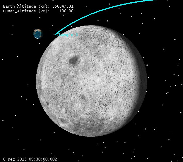
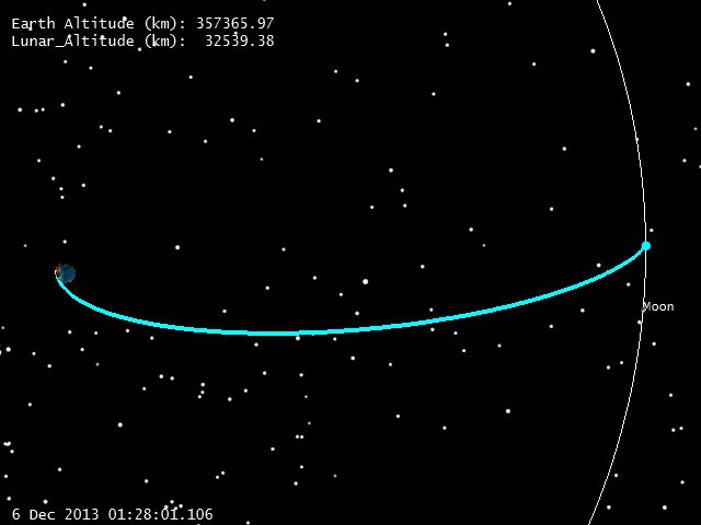
Earth-Centered View, C-3 at 5 Dec 2013 17:32 UTC (Click to zoom)
Earth-Centered View, C-3 at 5 Dec 2013 17:32 UTC (Click to zoom)
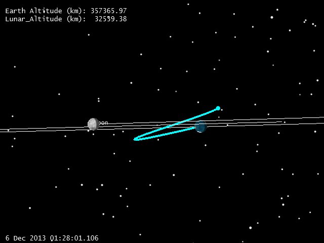
This gives us a good idea where C-3 is now, but what does the rest of the trajectory look like? First let’s look at the LOI geometry.
Chang’e 3 LOI Geometry (Click to zoom)
Note that with a 5 day transfer(4.8 really, 116 hrs) the approach to the Moon comes from the side, with respect to the Earth. This is a nice geometry for visibility at LOI, especially for a polar orbit, because it lets the LOI burn happen in full view of the ground. With equatorial spacecraft (LADEE) getting the LOI in view of the Earth can require a bit more work. It’s not a great geometry for watching the maneuver, given that there won’t be much radial-rate component, but it’ll do.
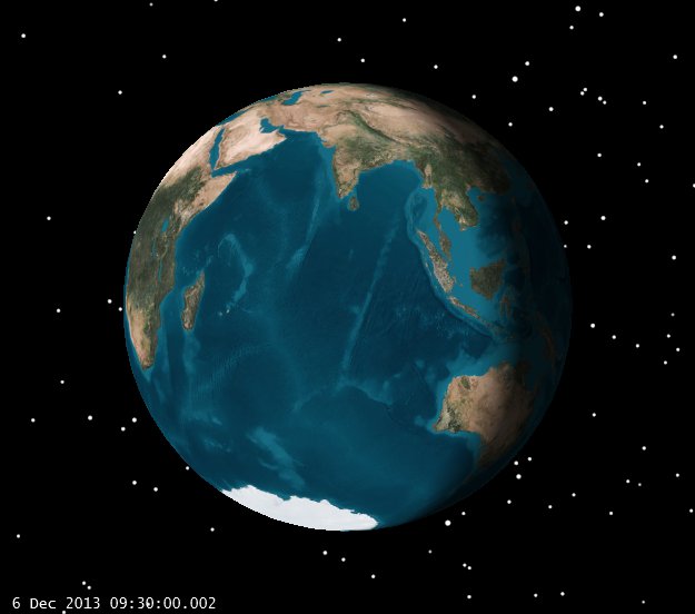
Now let’s take a closer look at the Earth to see what is visible.
View of Earth from Moon at LOI (click to zoom)
Without digging up the locations of the ground stations, it’s pretty clear that major portions of China are visible, as is Australia. Since we know Chang’e 3 is using some ESA stations, this is set up for a multiple ground stations to see LOI. Nice geometry for Orbit determination and real-time tracking of the event.
After one rev in Lunar orbit, we can see what the orbit looks like here:
Lunar Orbit 1 Rev past LOI (click to zoom)
The next question is, how does this set us up for landing? We have approximated the landing site at the Sinus Iridum region, with a Lunar Latitude of 43 deg N, and a Lunar Longitude of 31 Deg W. Note the lighting of that site at LOI:
Sinus Iridum landing site lighting at LOI (click to zoom)
Let’s look at the first day’s worth of ground tracks on the Moon, which will help us see what we’re waiting for, both in terms of lighting and geometry:
Chang’e 3 Ground track 1 day after LOI (click to zoom)
Note that the light blue line shows the incoming trajectory and the subsequent lines show the progression of ground tracks (which move from right to left). Further note that part of our ground track is in shadow (blue) as is the landing site, and part is in sunlight. Obviously, for landing we’d like sunlight both on the site and on our ground track. Here are the tracks a day later:
Chang’e 3 Ground track 2 days after LOI (click to zoom)
Our sunlit ground track on the right is moving closer to the landing site, and the shadow is drifting in the right direction as well. The trick here is to just wait in orbit while the Moon rotates under us. Looking at this in 3D gives a better geometrical perspective:
Chang’e 3 landing site and shadow geometry 2 days after LOI (click to zoom)
The orbit is pretty much fixed in inertial space, and we just have to wait while the Moon rotates. If we wait until Dec 15th we get this:
Dec 15 Lunar Ground Tracks (click to zoom)
Dec 15 Lunar Ground Tracks Zoomed (click to zoom)
At this point we’ve all but gotten lined up with the landing site, and it’s time to start the descent. Now we have to do a bit of guessing. We know that the descent profile goes from a 100 km circular orbit to a 100 x 15 km orbit (altitudes). We know that the vehicle lowers to periselene and then lowers from there. We’re going to assume that we won’t go a full rev in the 100 x 15 km orbit, but will instead just execute one half rev and descend. If so, it looks like this:
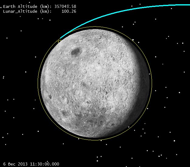
Descent Orbit Initiation to Peri (click to zoom)
It’s hard to show on this scale, but if you zoom and look closely at the left, you can see the orbit starts at 100 km (yellow) and then descends to 15 km on the right. Let’s look from the landing site perspective. Note we can see the approach hyperbola still (blue) the 100 km parking orbit (yellow) and the spacecraft at Periapsis just peeking over the limb at the top. You can see that the parking orbit isn’t completely locked inertially, it’s got a bit of drift in it from the Lunar gravity field.
Descent to Periapsis from Landing Site (click to zoom)
Now I have to really fake it. According to the superb site Spaceflight101, the landing engine actively throttles all the way down:
While I can model an engine that throttles, it’s way too much work (if I was working on the mission, I’d have the lander controls people do this) so I’m going to fake it with 2 constant thrust finite burns and a coast segment. I won’t bother trying to get masses and engine masses right either, I just want to show the basic idea:
C-3 Landing (click to zoom)
Of course the real profile won’t be exactly like this, but this is a reasonable facsimile. Let’s check out the geometry with respect to the Earth:
Earth Vector at Landing (click to zoom)
And finally let’s see what’s visible from Earth at the landing time:
View of Earth from Moon at Landing time
Which looks pretty darn good if you want to get coverage from Chinese ground stations. (Note: I lit the Earth up a bit in this picture to show what was visible, but this half of the Earth is in darkness at the landing.)
Pretty fun stuff. We welcome any updates, if anyone has better data than we do, it’s real easy to change the assumptions and re-run.
Part of an astrogator’s job is to determine the spacecraft’s current orbit, and predict where it will be in the future, just as the navigators on sailing ships figured out where their ship was and where they were going. Those navigators used star sightings, Sun observations, and accurate clocks to figure out their latitude and longitude. One of the ways they calculated their speed was to drop floats into the water and time how long it took for the ship to move a measured distance. On LADEE we also take observations and measurements to figure out where LADEE is. These measurements are called tracking data, which we receive from many ground tracking stations which are positioned around the world. We use large dish antennae from NASA’s Near Earth Network, NASA’s Deep Space Network, and from the commercial Universal Space Network. We schedule time each day for the various ground stations to track LADEE, using radio signals, and they send us tracking data files containing their measurements during and after the pass. In these files we can get the ground station’s observations of the distance to the spacecraft (“Range”); the speed at which the spacecraft is moving towards or away from the ground station (“Doppler” or “Range Rate”); and the angles in the sky where LADEE is, from the ground stations’ point-of-view. We don’t always get all these types of measurements, nor do we get tracking data all the time, but we don’t always need to. (We will never say no to more tracking data, though. We like it when the controllers schedule extra time to communicate with the spacecraft because then we get more tracking data! We often exclaim, “More Data!”) After we get the tracking data, we use a first guess at what we think the orbit is currently, and we estimate a new orbit by adjusting the trajectory slightly to fit the new measurements. We use AGI’s Optimal Extended Kalman Filter, (in Orbit Determination Tool Kit, aka “ODTK”) to read these files and estimate LADEE’s orbit. We’ve used this on many other cislunar and Earth orbits before, and it really works great!
The end result of our orbit determination work is a spacecraft ephemeris file of where LADEE has been in the past, and another ephemeris file of the predicted orbit, which is where we think LADEE will be in the future. The ephemeris file of the past trajectory is sent to the scientists who need to know where LADEE was when it took their science measurements. The predicted ephemeris file is used by the mission planners for scheduling their activities. It’s also used by other astrogators to calculate “acquisition” data to send to the ground stations so they know where and when to point their antenna to track LADEE. And it’s used by other astrogators to plan the next orbit maneuvers and attitude orientation plans.
It’s very important that we calculate accurate orbits, and we have some pretty tight requirements on how accurate our past orbit knowledge must be, as well as how accurate our predicted orbit must be. As you might imagine, since the tracking is done using radio waves, the signals can have noise on them. The signals are affected by things like weather (one of the ground station dishes was struck by lightning a few weeks ago!). The electronics on the spacecraft also are affected by the harsh temperature changes in space. To make sure our orbit is accurate we spend a lot of time “tuning” the filter settings. This includes identifying and throwing out bad data, calculating how much noise is on each measurement, and calibrating bias values for the various tracking electronics. Also, every time there is a maneuver, whether a large orbit burn, or a small momentum dump, we have to calibrate that maneuver and estimate its exact magnitude and direction. It’s been very rewarding working with the other LADEE astrogators that do this orbit determination work: Craig Nickel, Ryan Lebois, and our Orbit Determination lead, Lisa Policastri. They have done a great job, preparing for years before we launched, and since have been working long hours on crazy shift schedules during operations to make sure we know where we are and where we are going! We have a lot of discussions on how the data look, what the biases might be, and things to try to make our orbit solutions better. (Some conference papers we’ve written describing the details of how we’ve done Orbit Determination for other missions can be found at http://www.applieddefense.com/resources/white-papers/ )
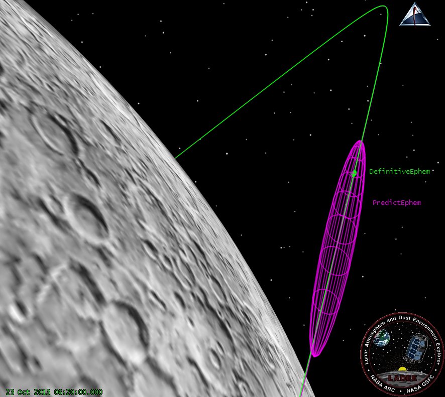
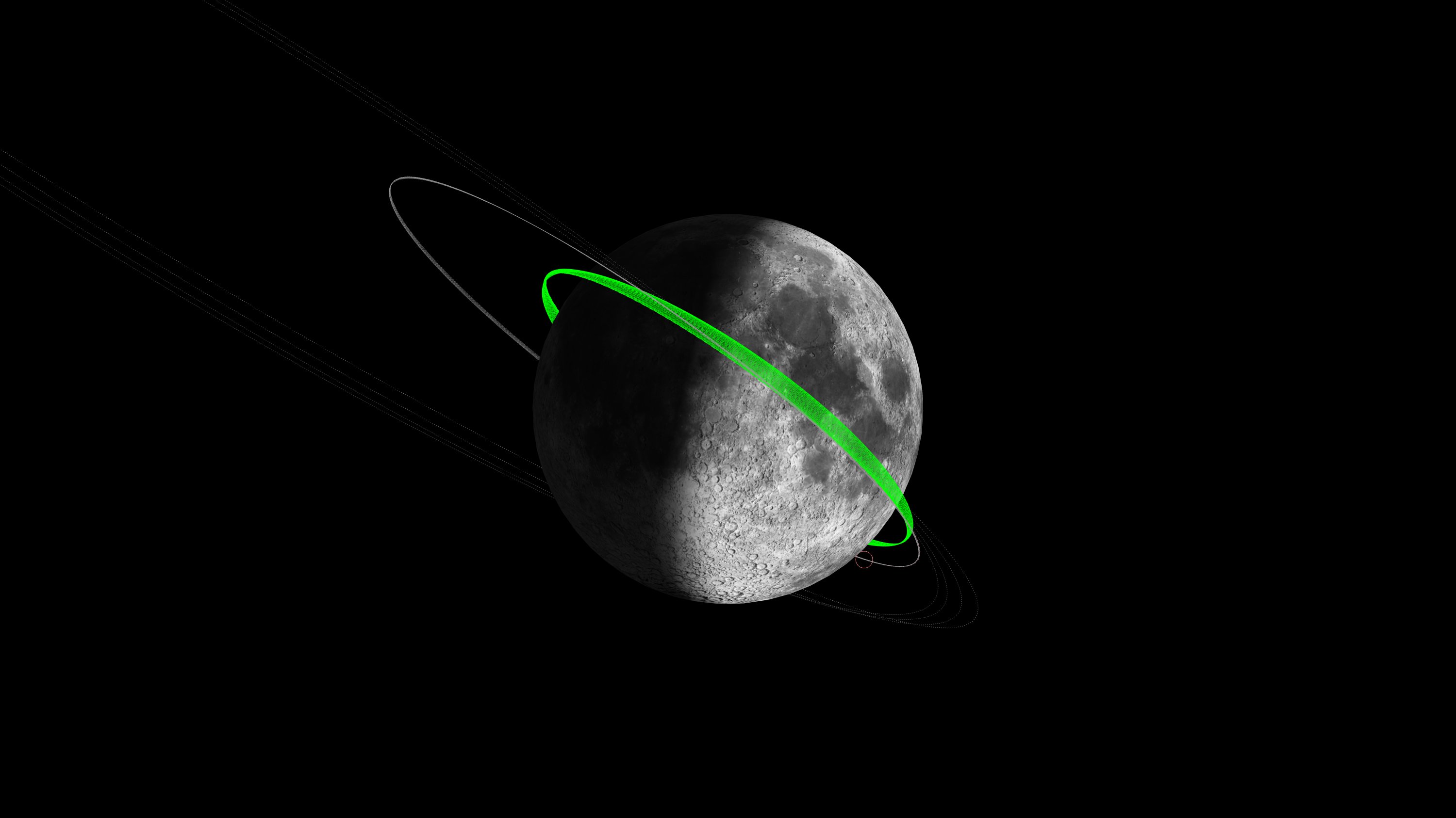
The LADEE OD team compares the orbit prediction (Purple) from a few days ago with the current solution (Green), making sure that the predictions are accurate enough to support communications and LLCD pointing activities.
After we get an orbit solution, we then go through a lot of self-consistency checks to convince ourselves that our orbit is good, and we check our previous predictions with new data to see how well we are doing (as shown in these figures.) It is frustrating, though, that we can’t just look out a window and see where LADEE really is! Sometimes it seems like we are flying a remote control airplane with a blindfold on, maneuvering by only listening to the sound of the engine as it gets closer or farther from us!
Every once in a while, though, we get a good indication that things are going well. For example, when we were getting ready for our first Lunar Orbit Insertion burn, we were sure everything was going well, but there’s still a lot of anticipation in the air…. we were leaving the Earth’s dominating gravity, and falling rapidly towards the Moon. (“Falling with Style” as Buzz Lightyear would say!) We designed LADEE’s trajectory to go behind the Moon and—based on our predictions—we planned the exact time for the main engine to fire to brake into Lunar orbit, igniting just a few minutes after LADEE became visible again from behind the other side of Moon. We sure hoped we got the prediction correct! In addition to estimating the time LADEE would lose signal as it disappeared behind the Moon, we also estimated the uncertainty in that time; we predicted we knew the time within 2 seconds. We were listening to the other team members on the voice loop, and we cheered as they called out that the Loss Of Signal was within 2 seconds of our prediction!
The LADEE OD team calculates the uncertainty of each orbit solution. One consistency check we perform is to see that the difference between the predicted and final orbit estimates are close compared to their uncertainties. The uncertainty of the predicted orbit is shown in Purple, and the uncertainty of the current “definitive” solution is in Green. In this case, the final definitive orbit and it’s uncertainty is completely within the predicted uncertainty. This is an indication that the prediction a few days ago is still good to use now.
“We thought the ground terminal would have to do a little searching, but it turned out it was pointed perfectly,” Boroson says. “We turned it on and all cheered.” The connection was almost instantaneous. After the spacecraft and ground terminal connected, a 4-inch laser beam travelled 238,000 miles from the moon to New Mexico.
Over the 239,000-mile distance between the Earth and the moon, the 4-inch-diameter laser column disperses to a width of 3.5 miles by the time it reaches the ground.
There was really little room for error: the pointing had to be correct, and the predicted ephemeris has to be accurate. Although we had done several tests prior to launch, sending test products to check out the system, we didn’t know how things would work until they turned on the LLCD system. You can imagine when we heard over the voice loops and in the status briefings last weekend that the orbit ephemeris was good enough that the system worked right away, and that they didn’t need to search, we were very excited!
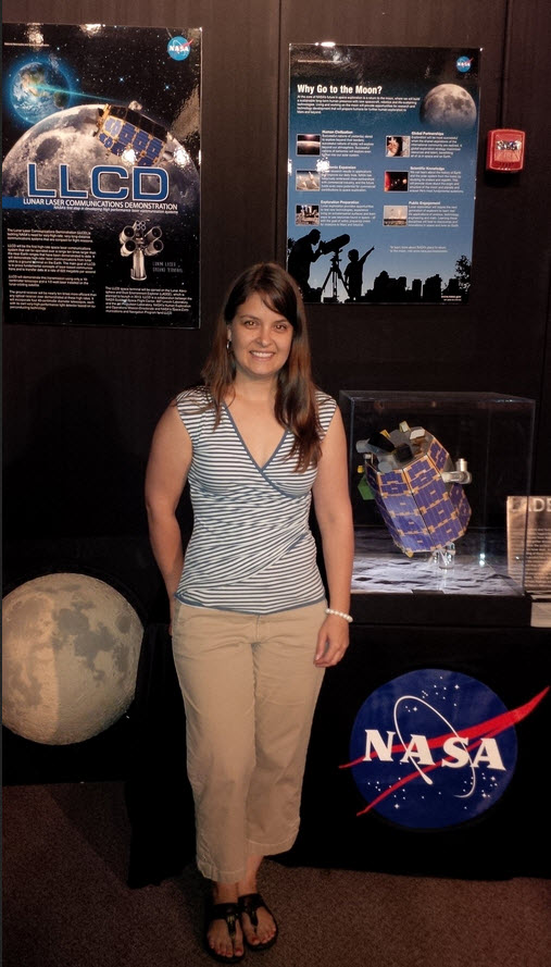
Our LADEE Orbit Determination lead, Lisa Policastri, visited the NASA Wallops Flight Facility prior to launch. She is standing here in front of the LADEE display, and you can see the LLCD display on the left.
The orbit determination team really did their job! And, in addition, our nine-person Flight Dynamics Team performed several other tasks to make the LLCD experiment work. We calculate the orientation (also called the “attitude”) of the spacecraft for the experiments. We also create the on-board spacecraft ephemeris so the LLCD instruments mounted on LADEE know where and when to point back at the ground terminals on Earth. And we generate the pointing angles for the ground terminals to point their LASERS at LADEE. Of course, we’re not the only ones… Our flight dynamics team sits in the room next to the activity planners, and the many sub-system engineers, and we are near the controllers, and the many other folks that worked through the weekend and over long nights at Ames to make this successful. It was an exciting weekend!
And that’s just listing some of the folks at NASA Ames. To see the rest of the LLCD team, check out the web page http://llcd.gsfc.nasa.gov – It really is great to see what can be accomplished when so many people, of very different talents, have a chance to work together, and try something new.
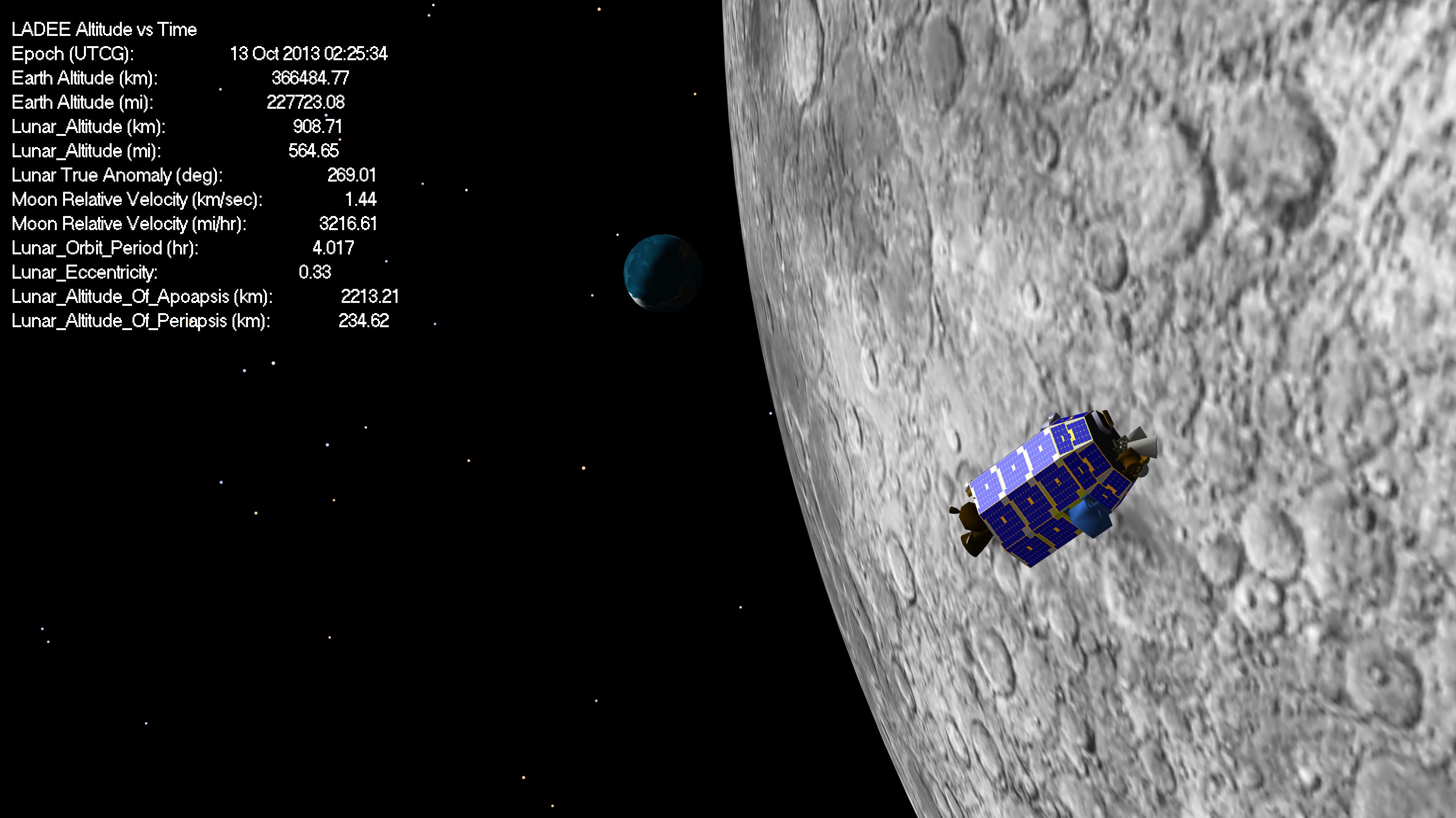
Sorry for the delay in updating, Astrogator_Mike had to make the long drive home after LOI-3 and get configured back in his home base. In the mean time, Lunar Orbit Insertion Burn 3 (LOI-3) was completed successfully (within 0.6% of target) on Oct. 13, 2013. LADEE’s post LOI-3 orbit had an aposelene altitude of 250 km, and a periselene altitude of 235 km. You can see below that this has evolved over time to 220 km x 260 km.
LADEE will now stay parked (i.e. no maneuvers) for roughly a month, while the spacecraft does alternating Lunar Laser Communication Demonstration (LLCD) tests, and calibration tests of the other science instruments.
Our Japanese friend on twitter @LadeeOrbiter posted this picture today:
This is way cool. It would make a great Halloween costume!
We understand that the twitter account is an unofficial site for lunar impact flash even monitoring by amateur astronomers in Japan to support the LADEE mission. The LADEE effort to involve amateur astronomers all over the world is supported by NASA, and I’d give you the link to their site about this, except that the site (like the rest of the US government) is offline.
We also have been told that the LADEE girl in the picture ( the LIMEM@STER) is a parody of a Japanese-made game called THE IDOLM@STER. You can see a bit of that here.
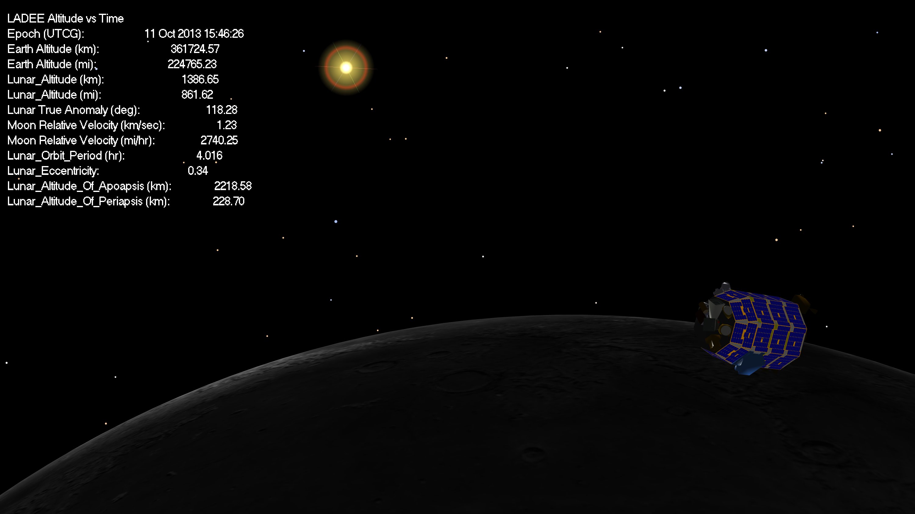
The LADEE Lunar Orbit Insertion burn 2 (LOI-2) executed as planned this morning at 3:38 PDT, placing LADEE into a 4 hr orbit. Things move much faster now for the spacecraft, and the Moon is looking a lot bigger. We originally captured with a periselene altitude near 560 km but our periselene has now been lowered to an altitude of ~235 km by Earth perturbations in the Post-LOI-1 24 hr orbit. The planned periselene of the commissioning orbit was 250 km, however the small (<1%) underperformance of LOI-1 caused aposelene to be slightly higher, and thus we got slightly more Earth perturbations than we nominally planned for. The result of this is that we got a bit of free lowering from the Earth, which we’ll take! (Since we plan to go lower than 250 km anyway). So the current plan is to drop the aposelene to 250 and perform commissioning there in the 235 x 250 km orbit.
LOI-2 lowered our apogee down to ~2200 (we’ll have to wait for some more tracking to verify that exactly).
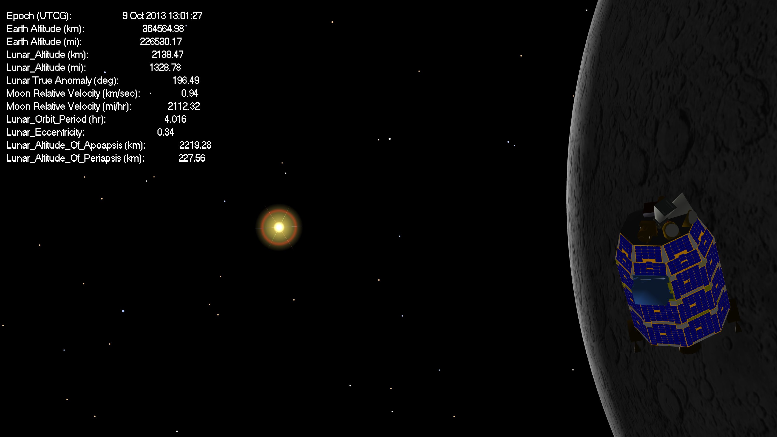
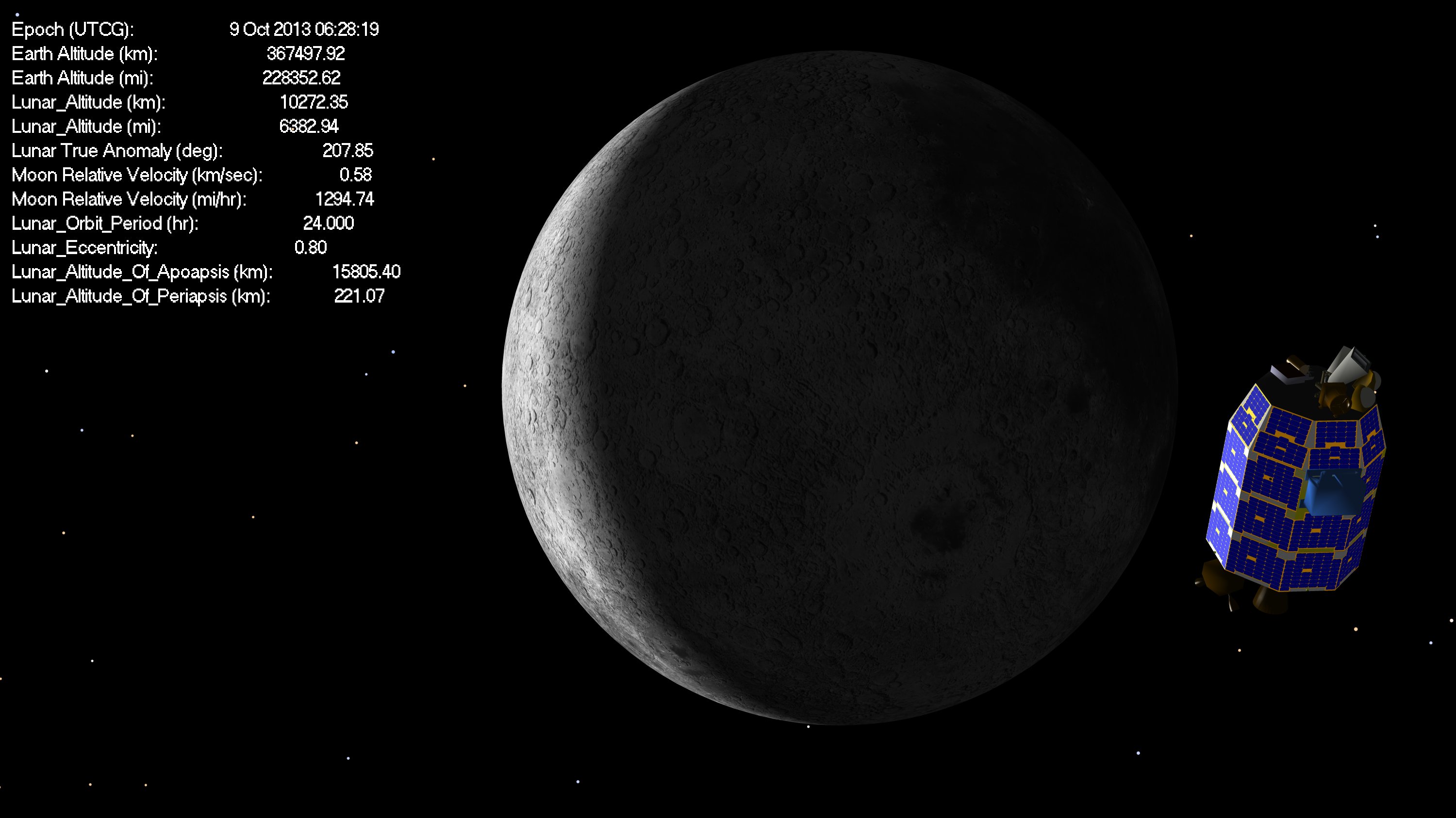
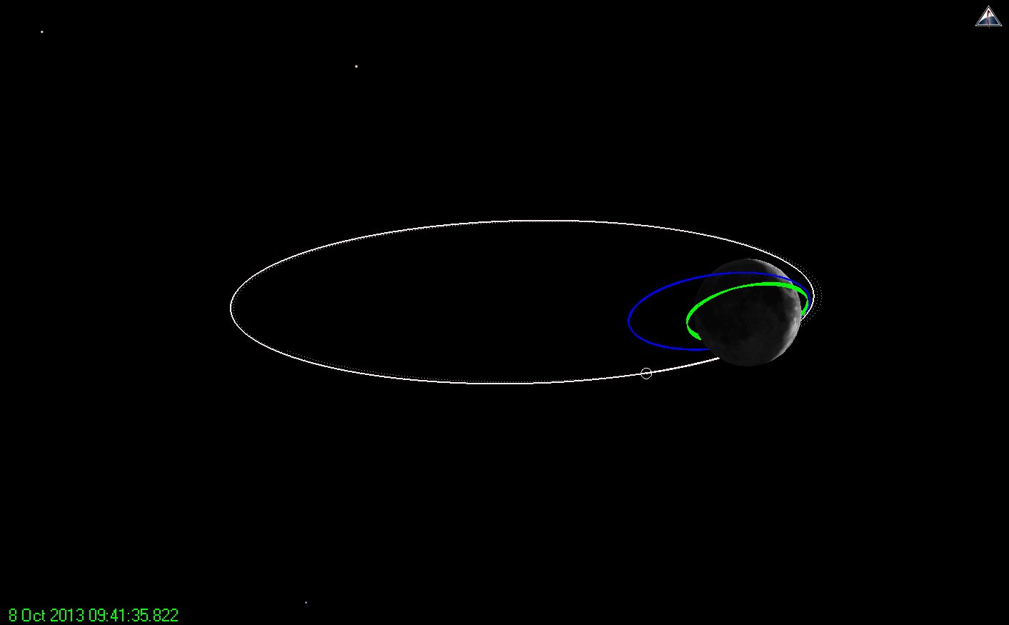
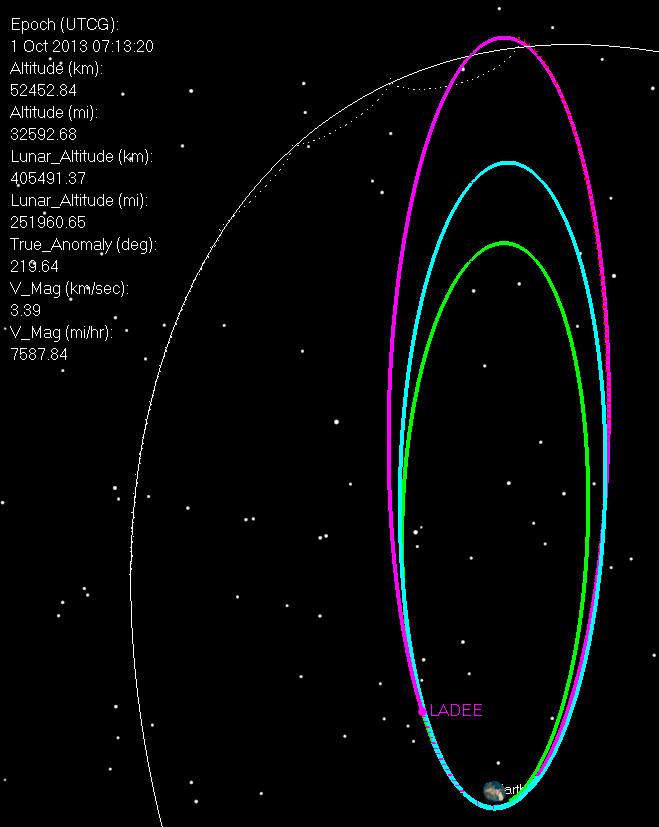
From our pre-LOI2 planning, things should now (9 Oct 2013 13:00 UTC) look like this:
And we are here in the orbit:
If you could see the orbit from Earth you’d see this:
Lunar Orbit Insertion Maneuver 2 (LOI-2) is upon us, scheduled for 09 Oct 2013 10:38 UTC. This maneuver will lower our periselene altitude from 15700 km down to 2220 km and change our orbit period from 24 hrs to 4 hrs.
The maneuver will last for 220.8 seconds, and will impart a delta-V (change in velocity) of 293 m/sec.
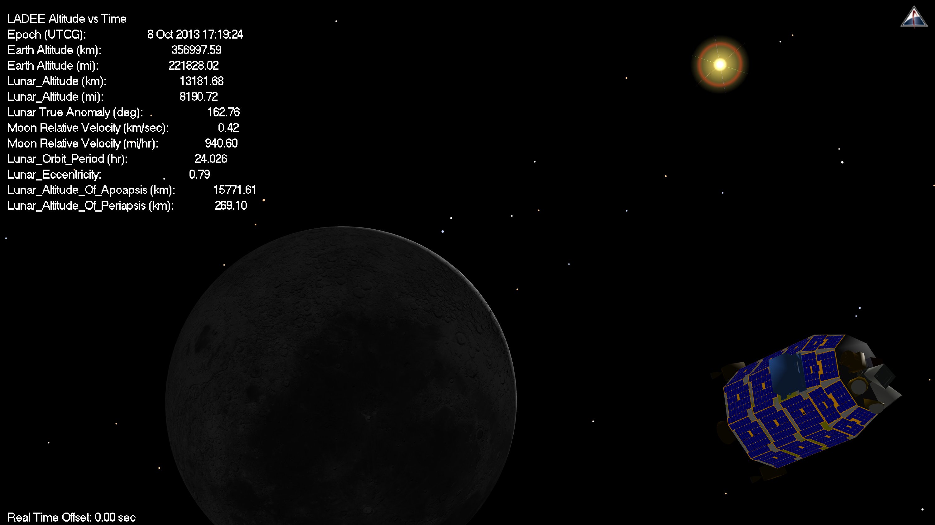
Right now LADEE sees this view:
And the orbit from above would look like this:
From Earth, if you could see the orbit, you’d see this:
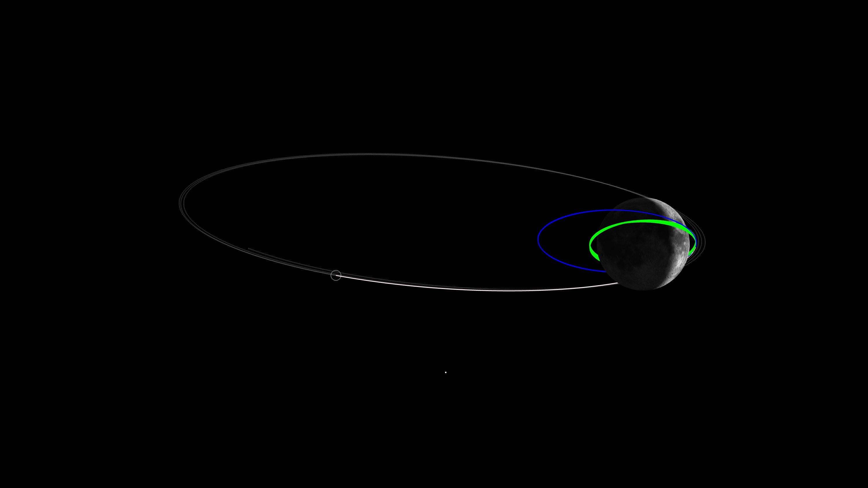
LADEE is now in its last rev in the 24 hour capture orbit, and preparing for LOI-2, which will lower the spacecraft into a 4 hr orbit. LOI-2 is scheduled for 10:38 UTC (3:38 AM PDT) Wed. morning, Oct. 9. Here’s the view from LADEE to the Moon:
Here’s the orbit [Note: blue shows the 4 hr orbit we’re going to next. Dotted lines show the past trajectory, solid are into the future. So we’re not quite at aposelene yet.]
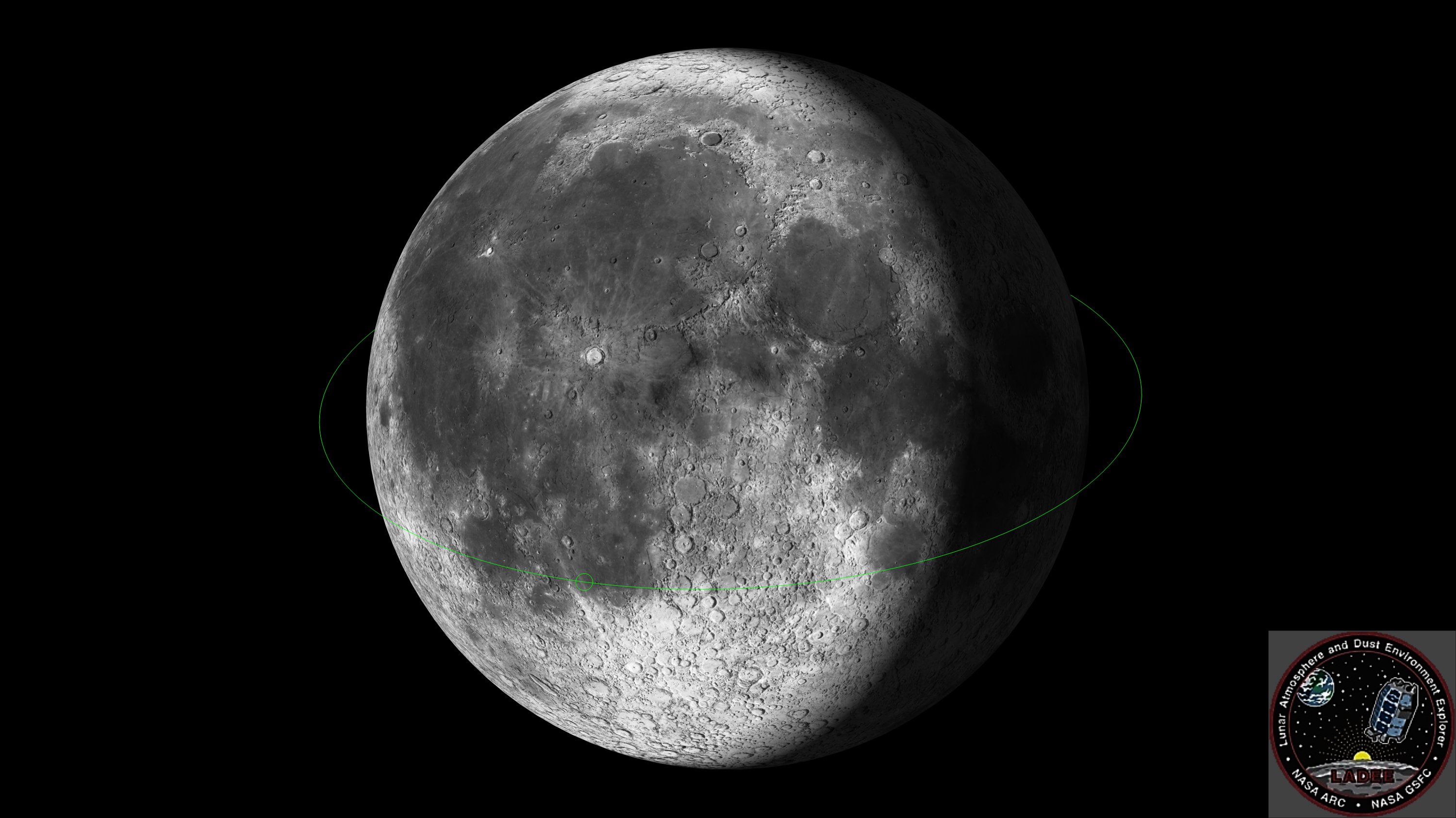
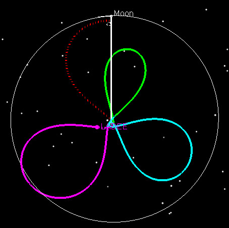
And finally the really cool view AstrogatorJohn came up with yesterday of the view of the orbit from the Earth:
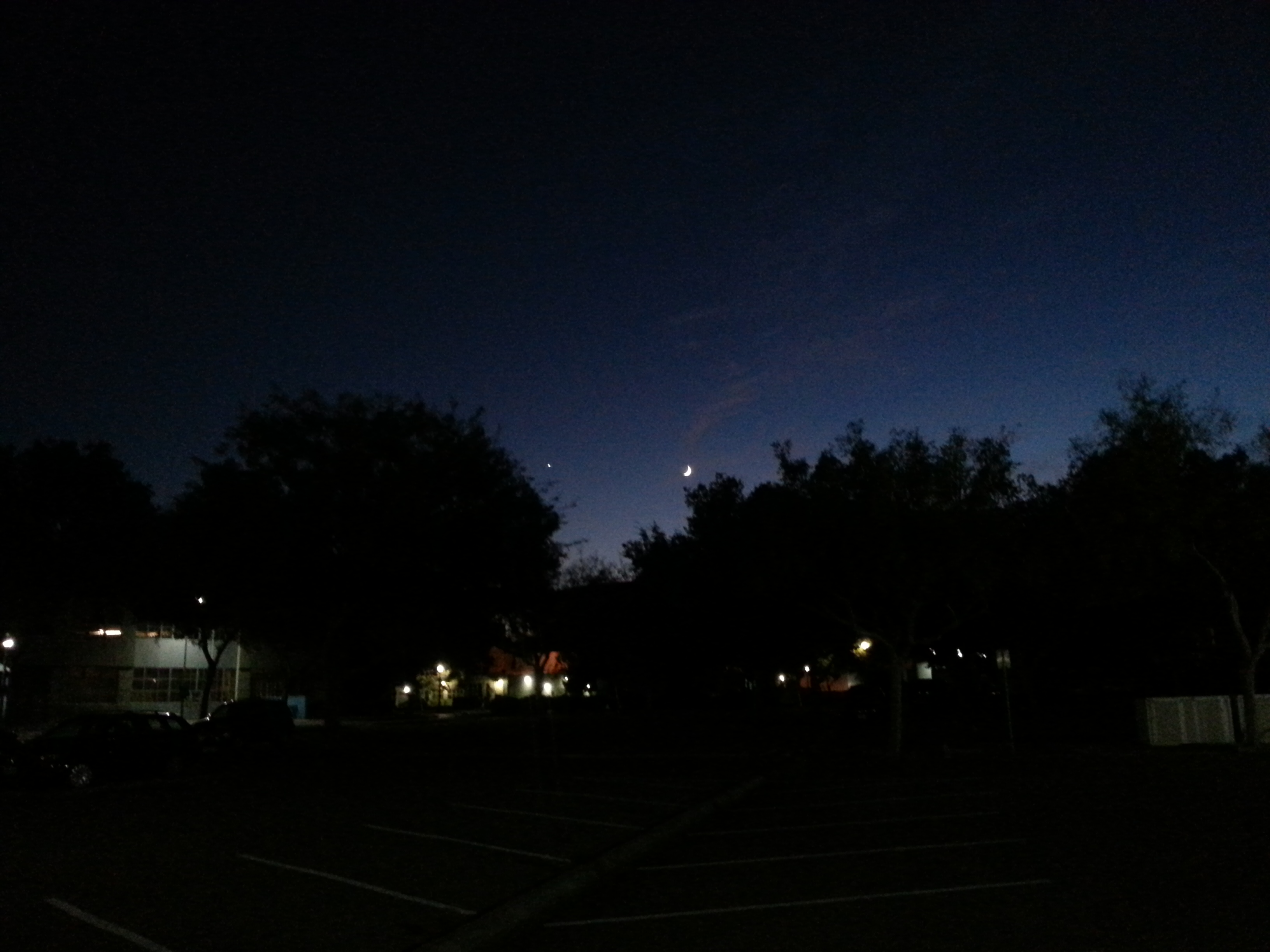
So if you go outside tonight and see the Moon, imagine this orbit.
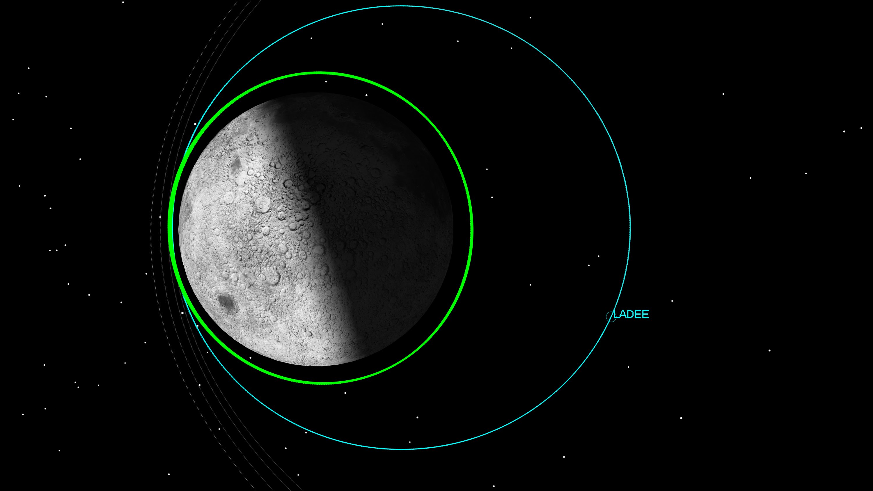
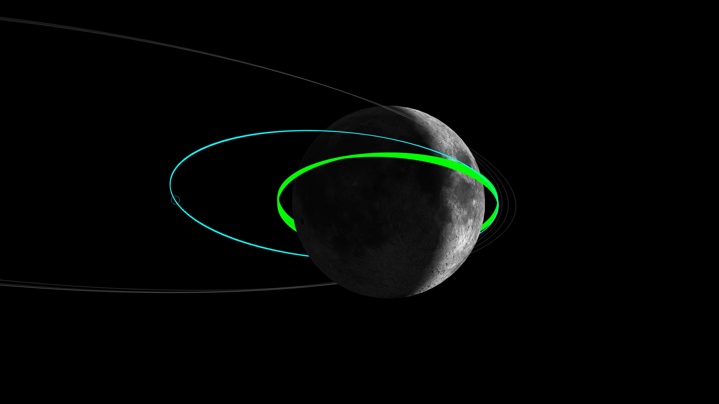
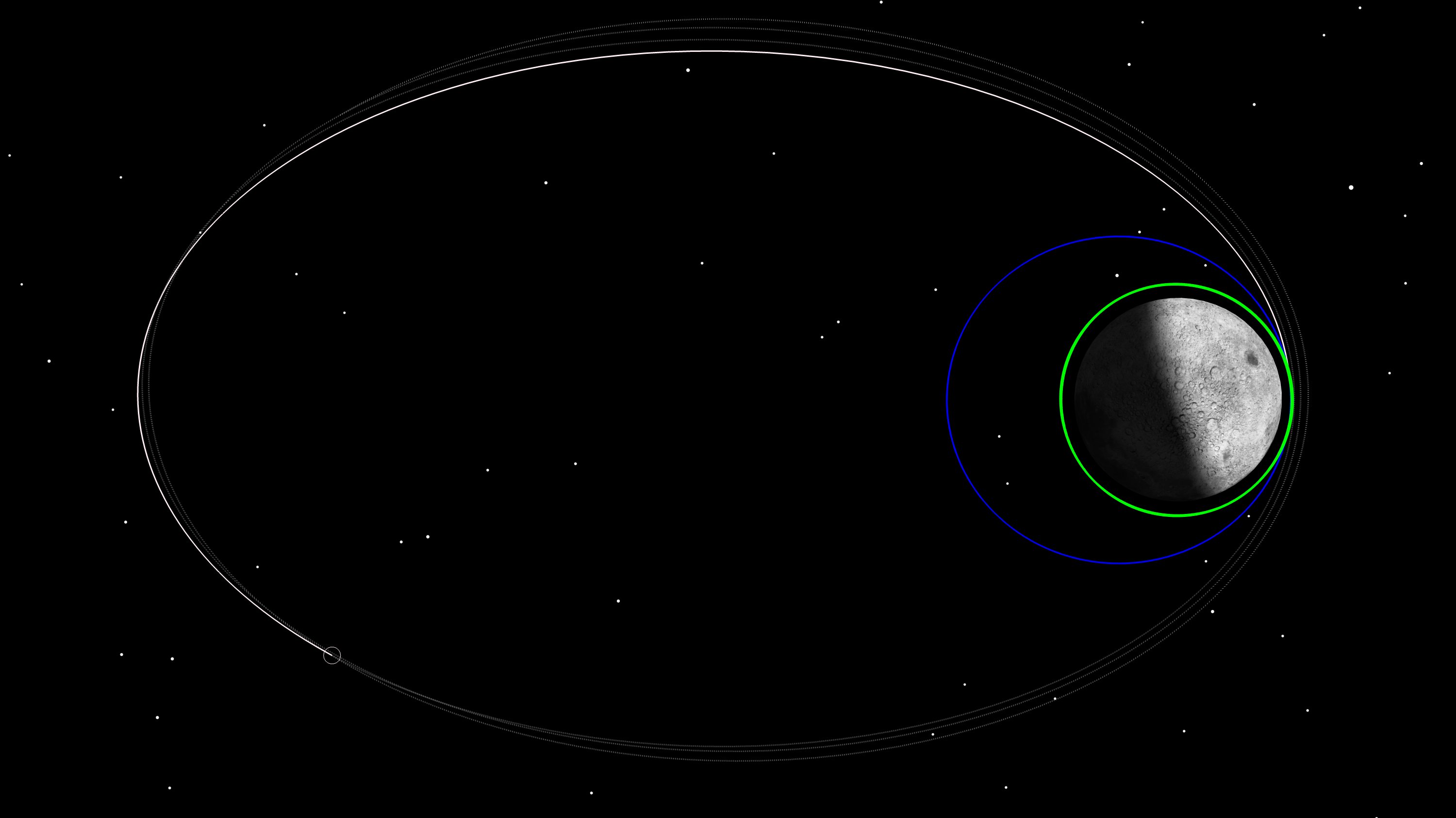
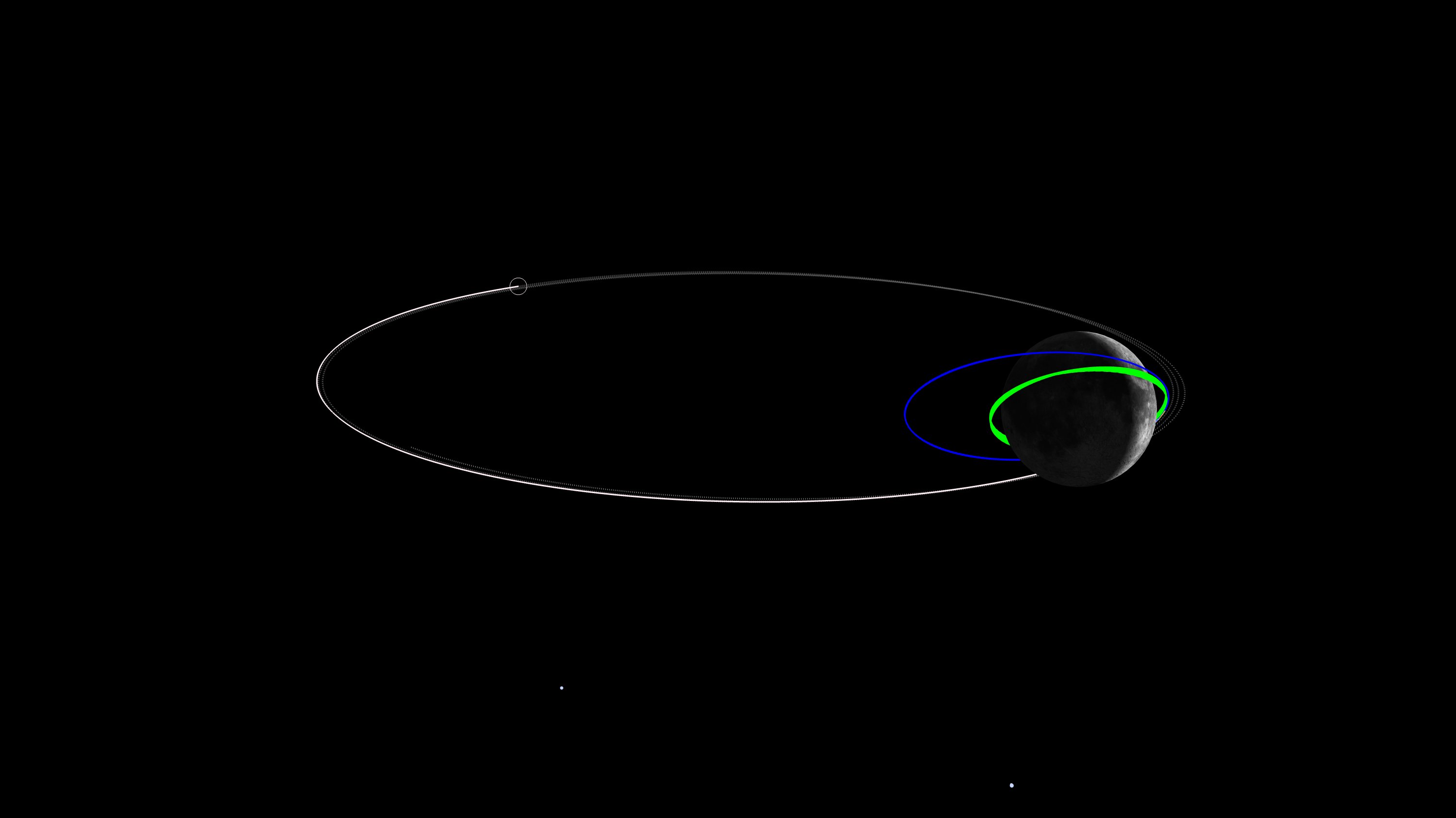
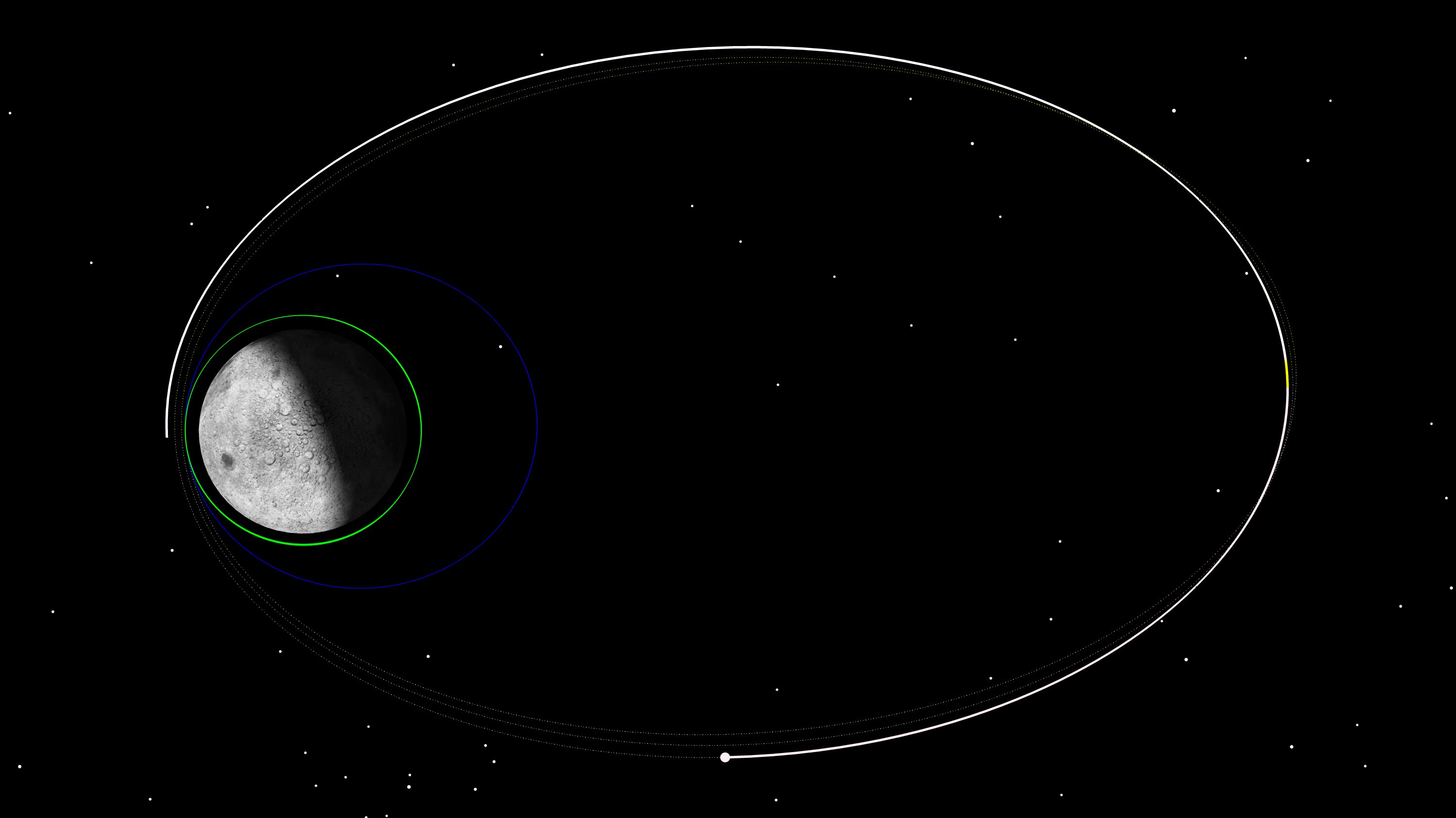
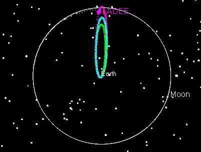
After posting the picture of the Moon from the parking lot at Ames, we thought it would be cool to see what LADEE’s orbit would look like, if we could see it, from the Earth. The picture below is from the Earth to the Moon, with Ecliptic North at the top. The White Orbit is our current orbit, and the small white circle is where LADEE was when I took this snap… it’s moving to the right, towards periselene; the Blue Orbit is what it will be after LOI-2, and the Green Orbit is the near circular orbit we will stay in during commissioning for about a month before we start science operations.
Astrogator Mike is in the Flight Dynamics Room planning our second lunar maneuver, Lunar Orbit Insertion-2 (LOI2), and I (Astrogator John) am processing tracking data doing orbit determination. Mike noticed the Moon and Venus over the parking lot, so I went out there with him took this picture with my phone. That’s Venus to the left of the Moon.
The LADEE Spacecraft successfully performed Lunar Orbit Insertion maneuver 1 (LOI-1) on Oct. 6, 2013 3:57 PDT. The LOI-1 maneuver captured LADEE into a 24 hr orbit. After 3 days (and 3 revs) in the capture orbit, the spacecraft will perform LOI-2 on Oct. 9 at 3:37 PDT. The second of 3 Lunar Orbit Insertion maneuvers, LOI-2 will reduce LADEE’s orbit down to a 4 hr orbit.
Finally, LOI-3 will be performed Oct. 12 at 8:00 PM PDT to circularize the spacecraft in a 235 km orbit. LADEE will spend a month in this “commissioning” orbit, while the spacecraft is checked out before full-time lunar science begins, and the Laser-Communications experiment will be tested.
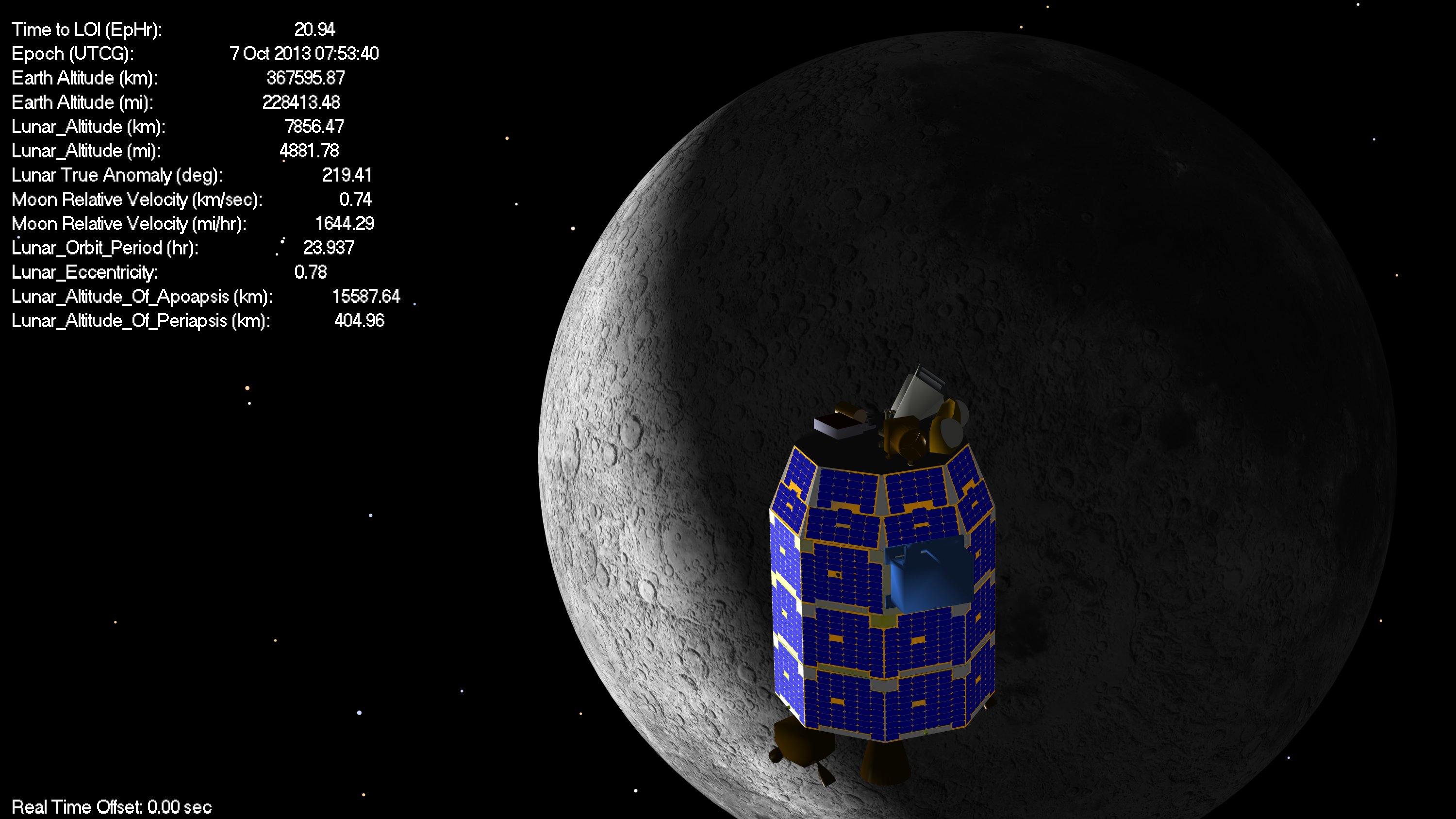
At this time (7 Oct. 2013 7:53) LADEE is past its first aposelene, and is headed for its first periselene after capture.
The LADEE spacecraft is now in Lunar orbit. Tracking data will later confirm the precise parameters of the orbit, but based on telemetry of thruster performance and accelerations, the LOI-1 burn appears to be close to nominal.
The planned Lunar orbit has an orbit period of 23.1 hrs. The next planned maneuver (Lunar Aposelene Maneuver 1, or LAM1) is scheduled for the 2nd aposelene, which would occur roughly 1.5 days from now. For LOI-1 results close to nominal, this maneuver can be waived.
LOI-2 is nominally scheduled for 3 revs after LOI-1.
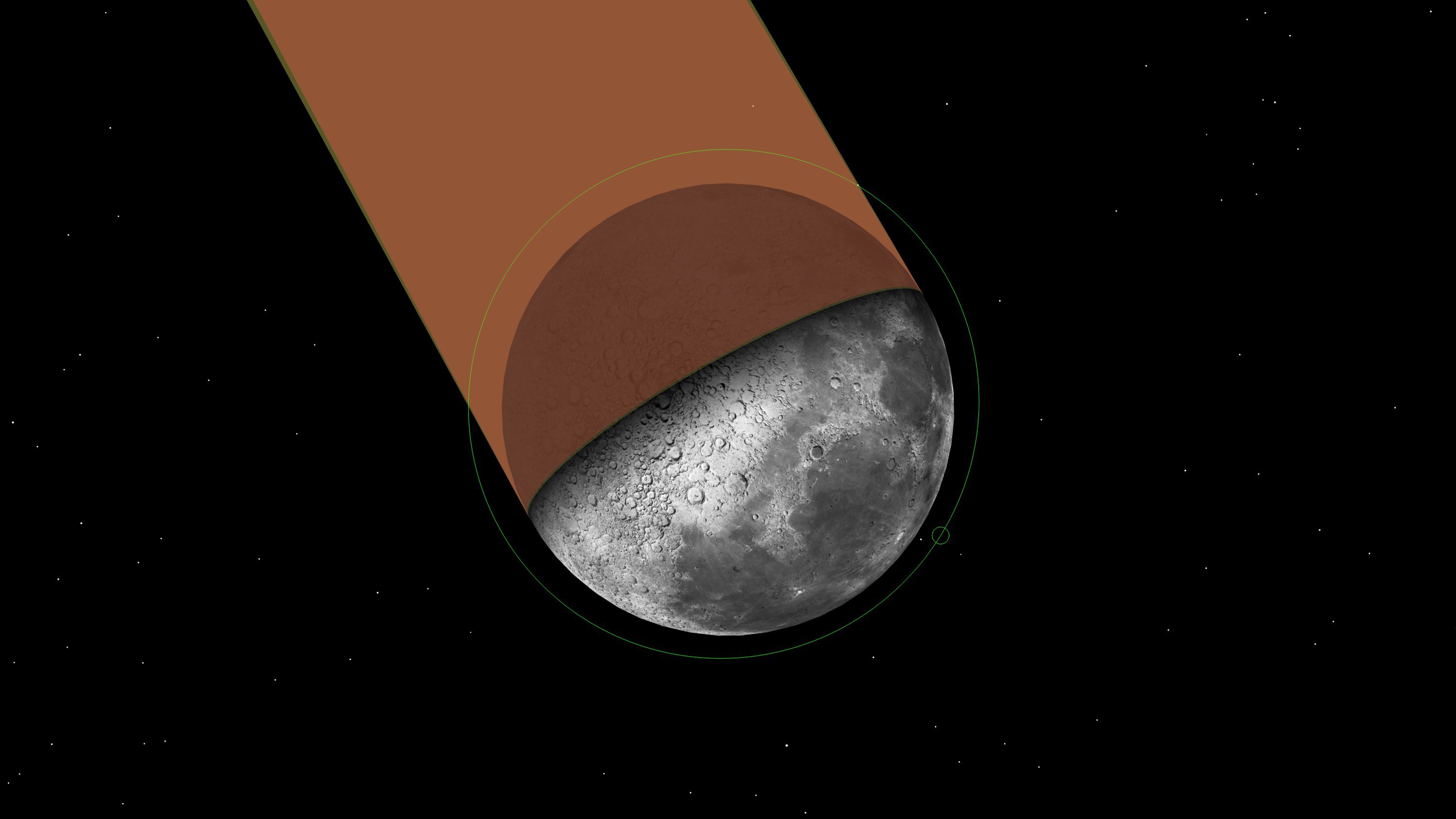
The Moon is now under control. Based on LADEE’s altitude (below 66,000 km) the Moon is now the primary gravitational body acting on the spacecraft. In other words, the Moon’s gravity is now stronger than the Earth’s.
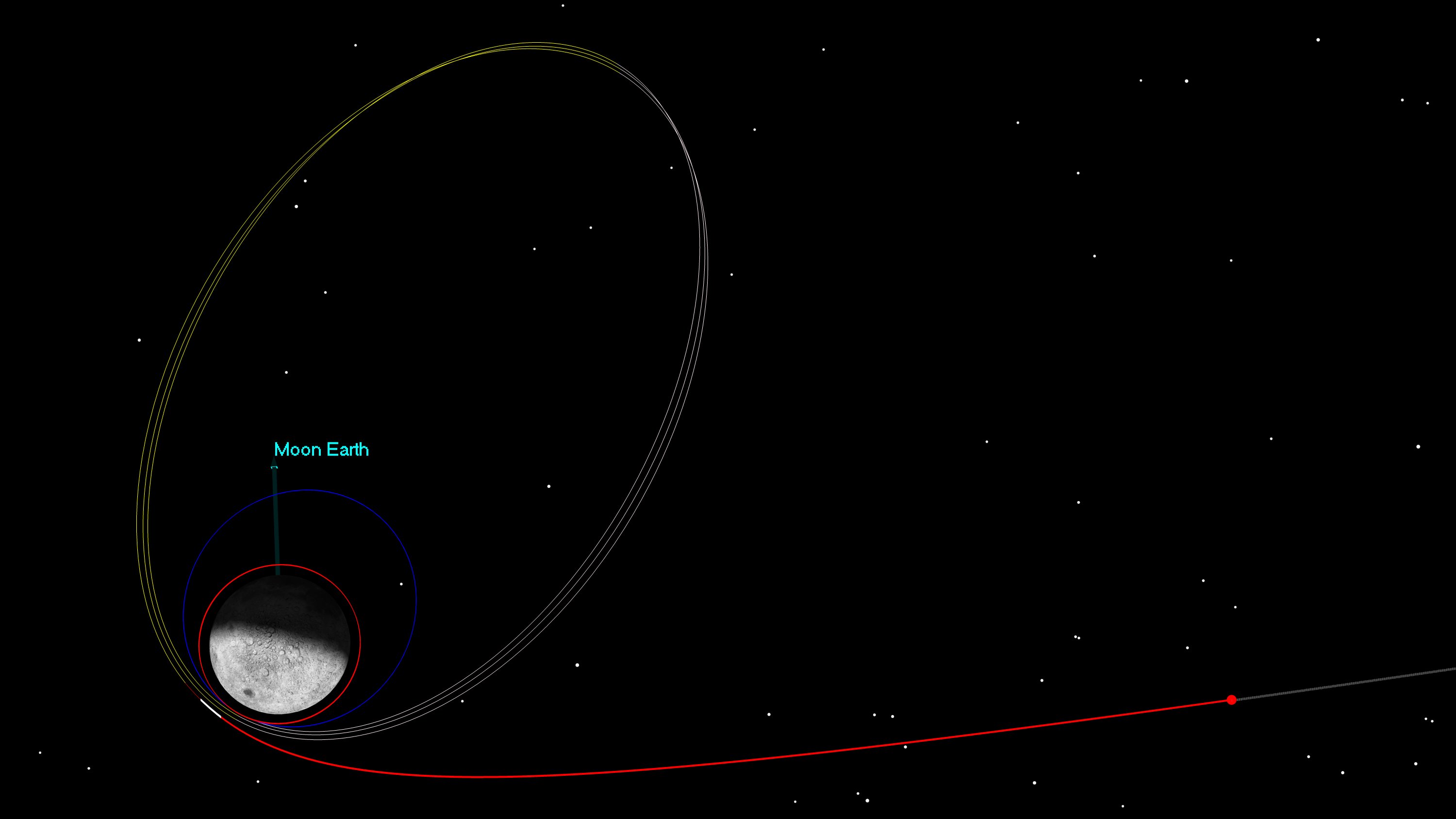
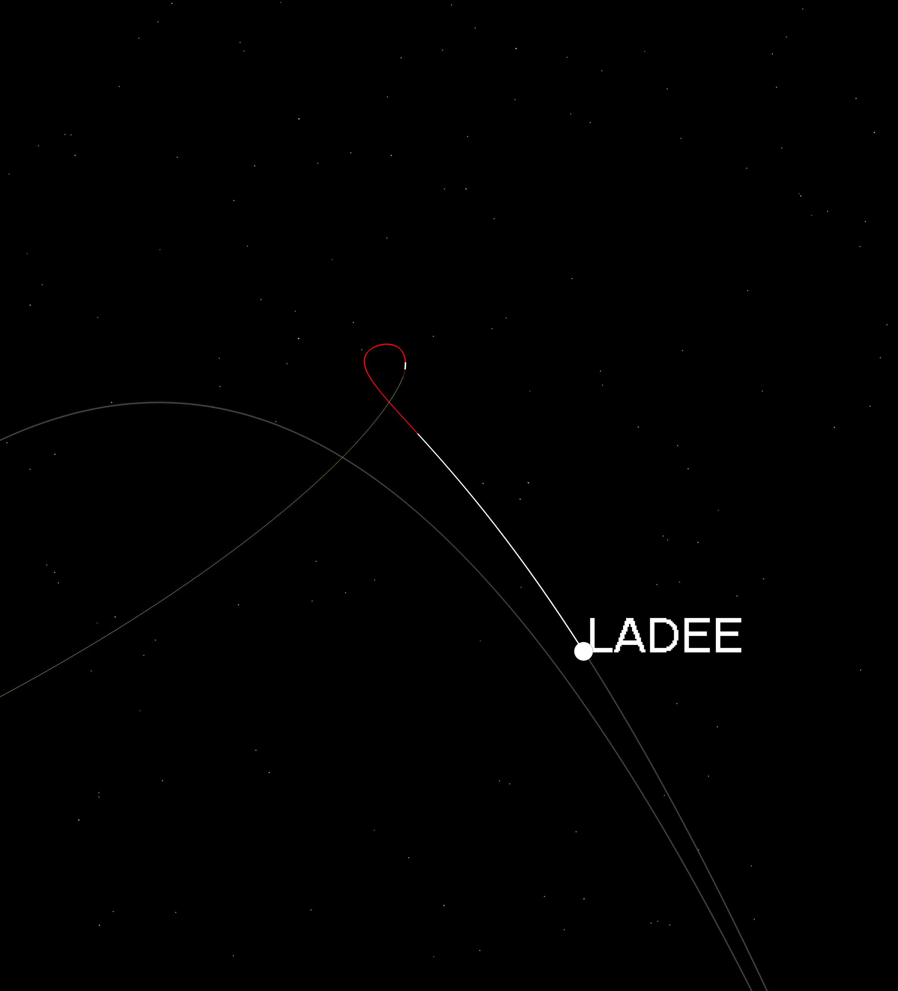
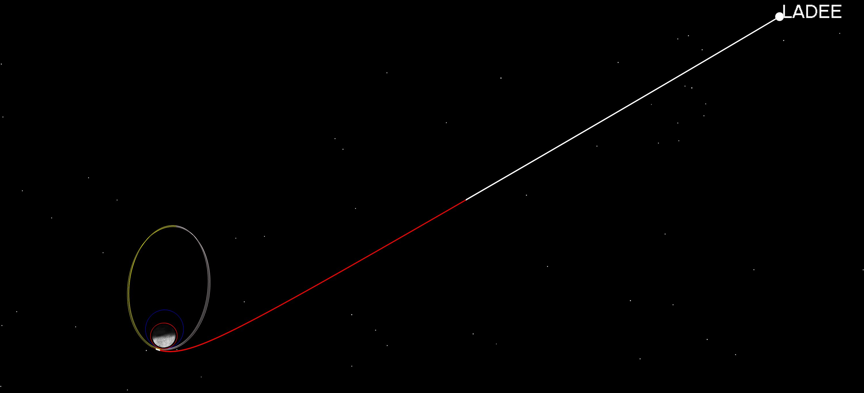
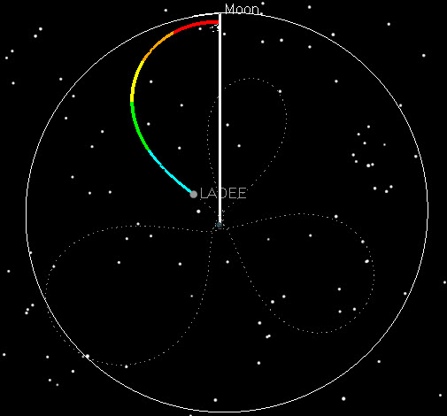
This picture really shows the change the Moon is imposing on the orbit, which until now had been a large elliptical orbit around the Earth:
Note that the white arc LADEE is currently on turns red when LADEE gets below 50,000 km. After that, you can see another short, white arc on the trajectory which is Lunar Orbit Insertion 1, or LOI-1.
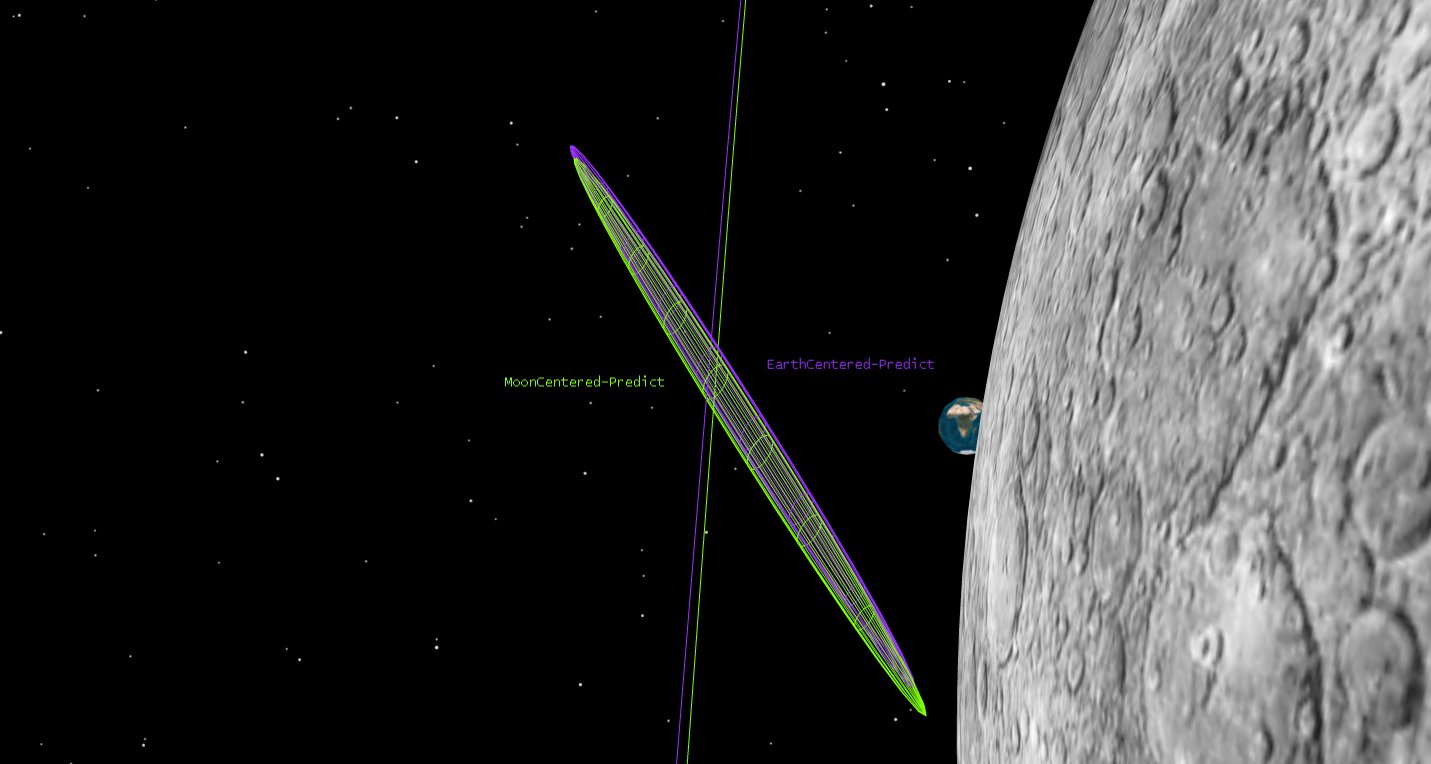
This figure, created a few days ago, shows the Earth- and Moon-centered orbit estimates. It also shows the uncertainty in these estimates. The uncertainty is very small, although it’s hard to see the scale in this picture since we zoomed in to show it. The uncertainty is shown as a 3 dimensional region in space that represents where LADEE is most likely to be. The region in the picture is only a few hundred meters long, using the estimate from several days ago (it’s smaller now).
As we mentioned previously, we’re not quite within the Moon’s sphere of influence yet. (LADEE will be within most definitions of the Moon’s sphere of influence by 19:30 UTC today, October 5th.) Even so, we’ve been modeling the significant effects of the Moon’s gravity on our trajectory since we launched. The way we modeled it, as is standard, was as if the Moon is a perfect sphere. In reality, however, we know from all the previous lunar missions that the Moon’s gravity field is quite “lumpy” and when we are in orbit around the Moon, we will model the Moon’s gravity with many more equations than we did when LADEE was close to Earth. As we approach the Moon, we have to transition from considering the Earth’s gravity as dominant to the Moon’s gravity as the primary effect. For trajectory design purposes we’ve been switching from an Earth-centered orbit propagation to a Moon-centered orbit propagation when LADEE gets within 50,000 km of the Moon’s center. (Our analysis has shown that this number doesn’t have to be very precise to meet the accuracy requirements. On the Clementine lunar mission we didn’t switch to a Moon-centered orbit propagation until we captured at Lunar Orbit Insertion.)
In addition to calculating the trajectories, we also have to track LADEE and estimate the orbit, using a technique called “Orbit Determination.” Fellow Astrogators Lisa Policastri, Ryan Lebois, and Craig Nickel work with us on this. The method we use is an Extended Kalman Filter, which processes tracking data sequentially as we receive the data from the tracking stations around the world. Orbit Determination is sort of like curve fitting, and one of our jobs is to estimate the trajectory that best fits the tracking data. As you can see from the pictures we’ve posted previously, LADEE’s trajectory bends a lot as it goes from the Earth’s influence to the Moon’s. To model the changing gravity for Orbit Determination, we decided to do something different than we do for trajectory design. Instead of switching from Earth-Centered to Moon-centered at a specified point, a few days ago we started running two algorithms side-by-side; one Earth-centered, and one Moon-centered. We trend the two different orbit estimates, and by the time we reach the LOI1 maneuver (6 Oct 2013 10:57 UTC), which is just past periselene, we will be ready to transition to using the Moon-centered algorithm for the rest of the mission.
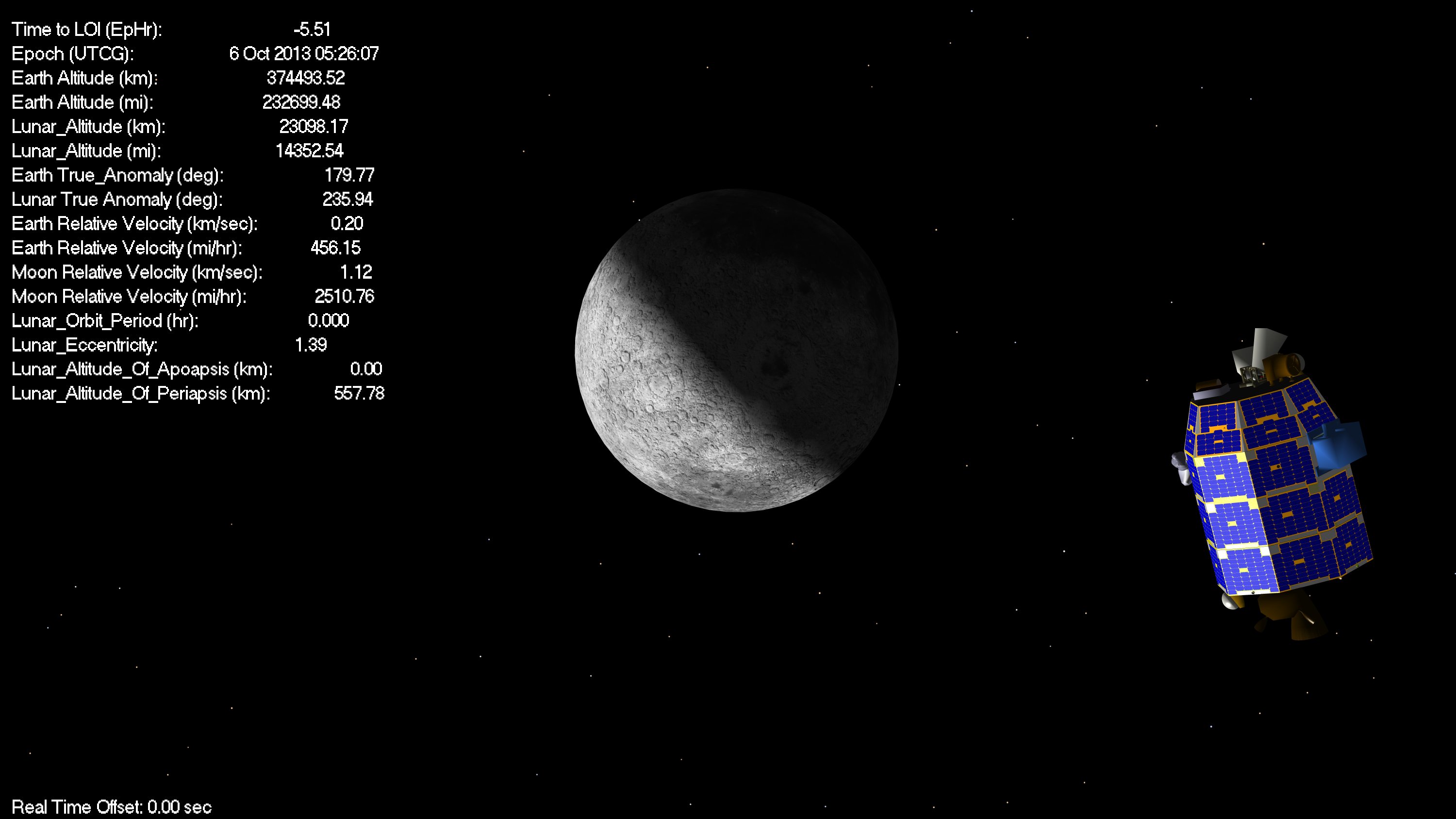
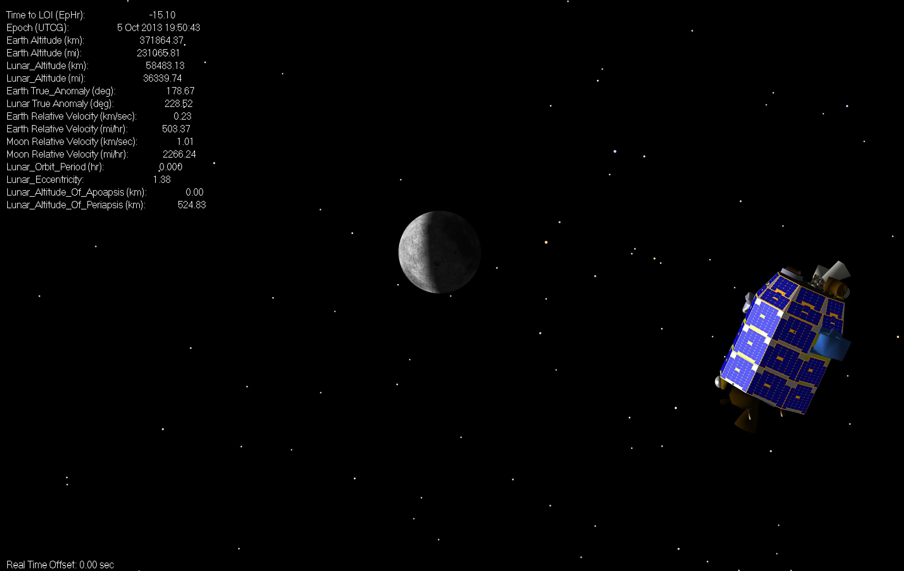
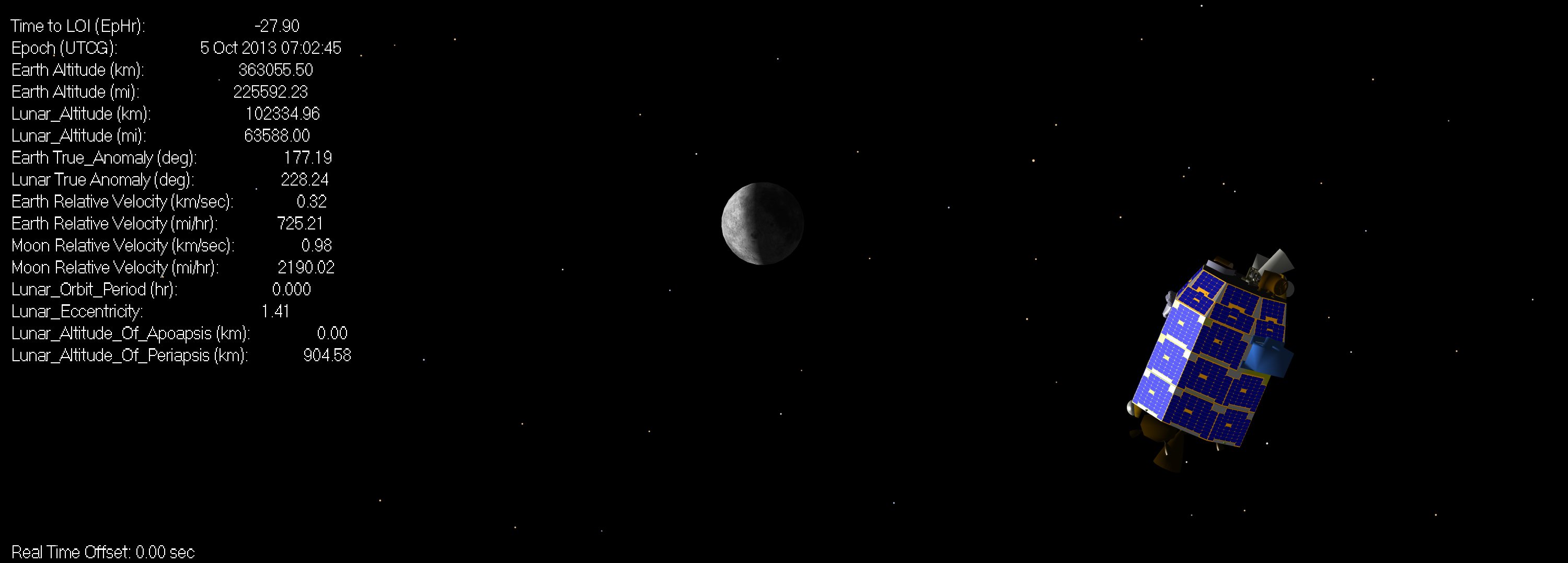
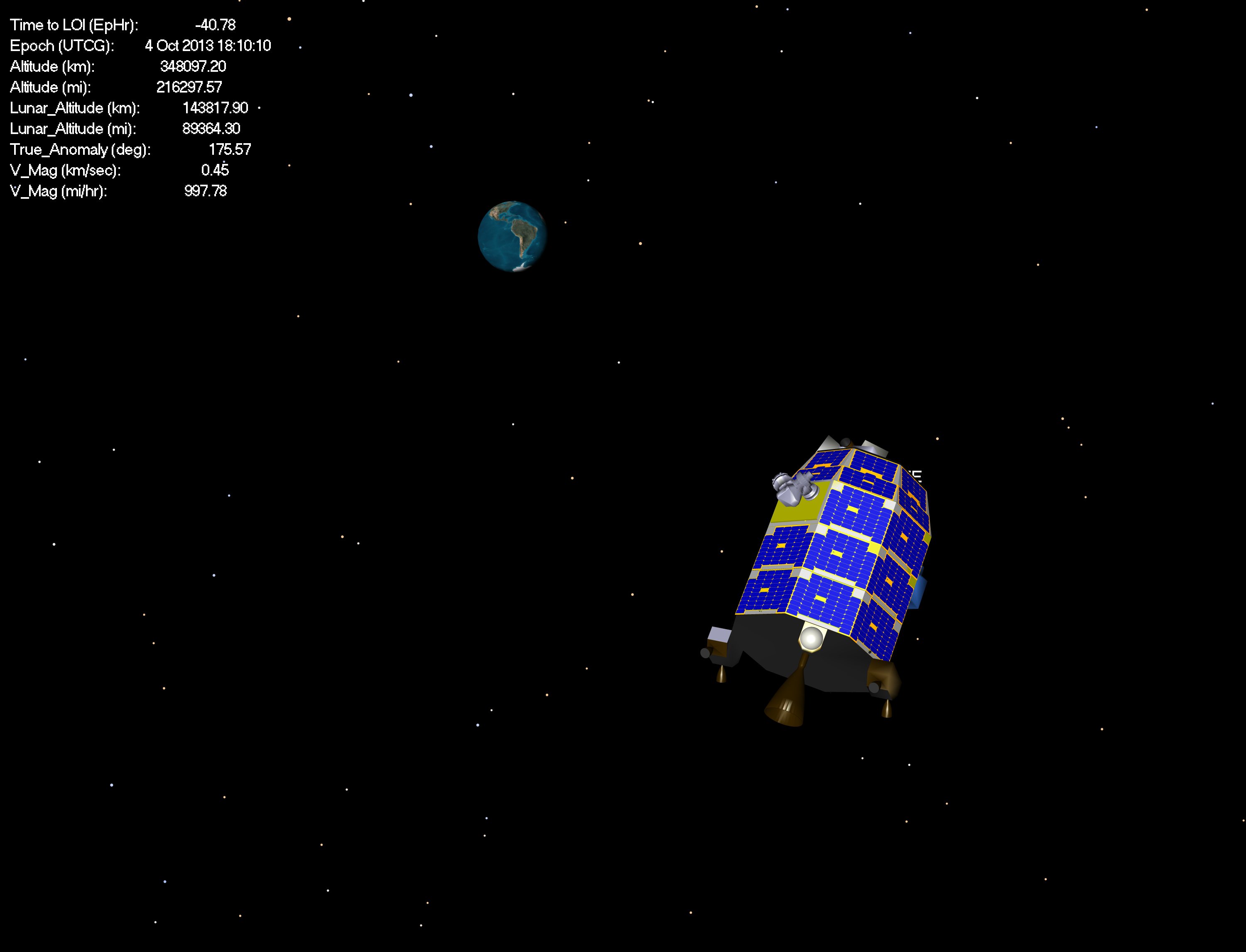
LADEE continues to approach the Moon, now nearing 100,000 km in altitude.
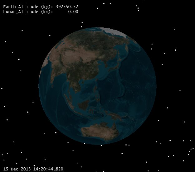
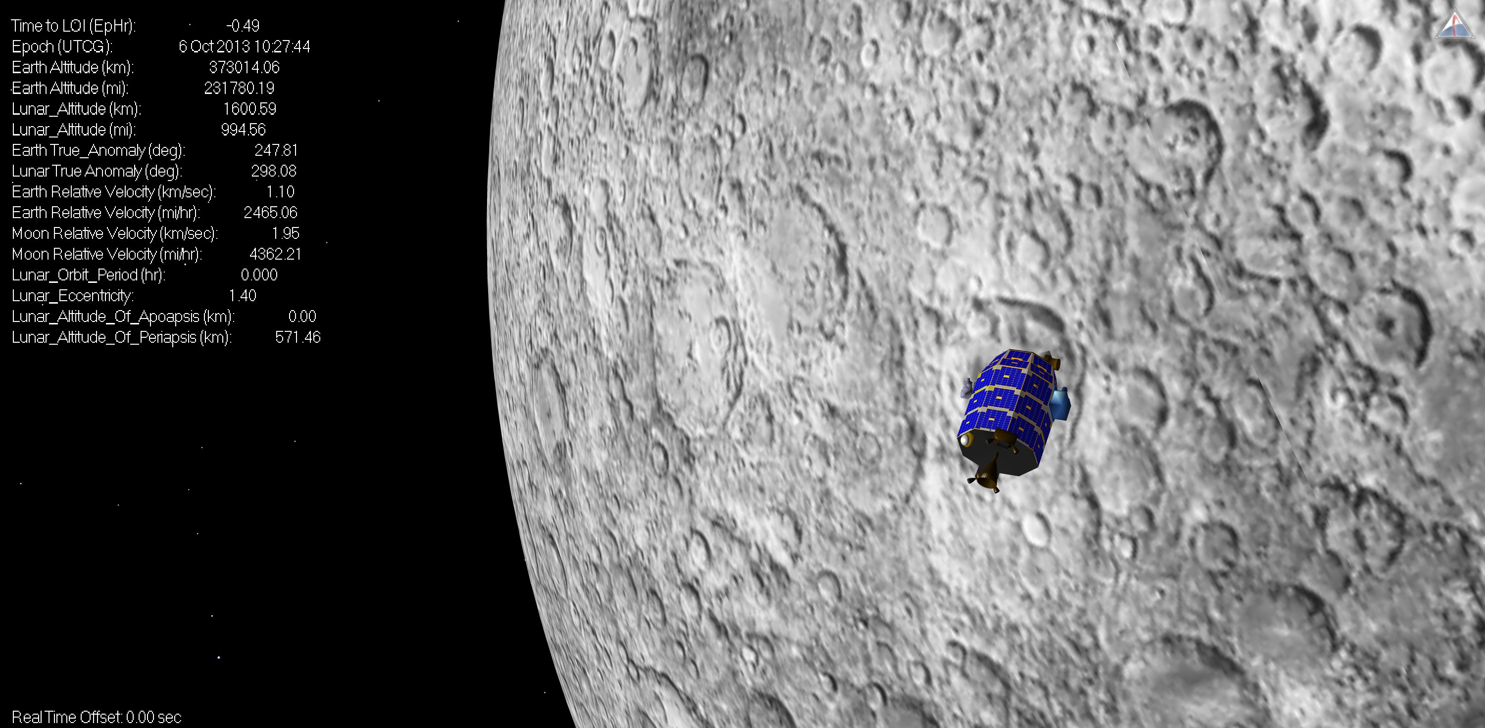
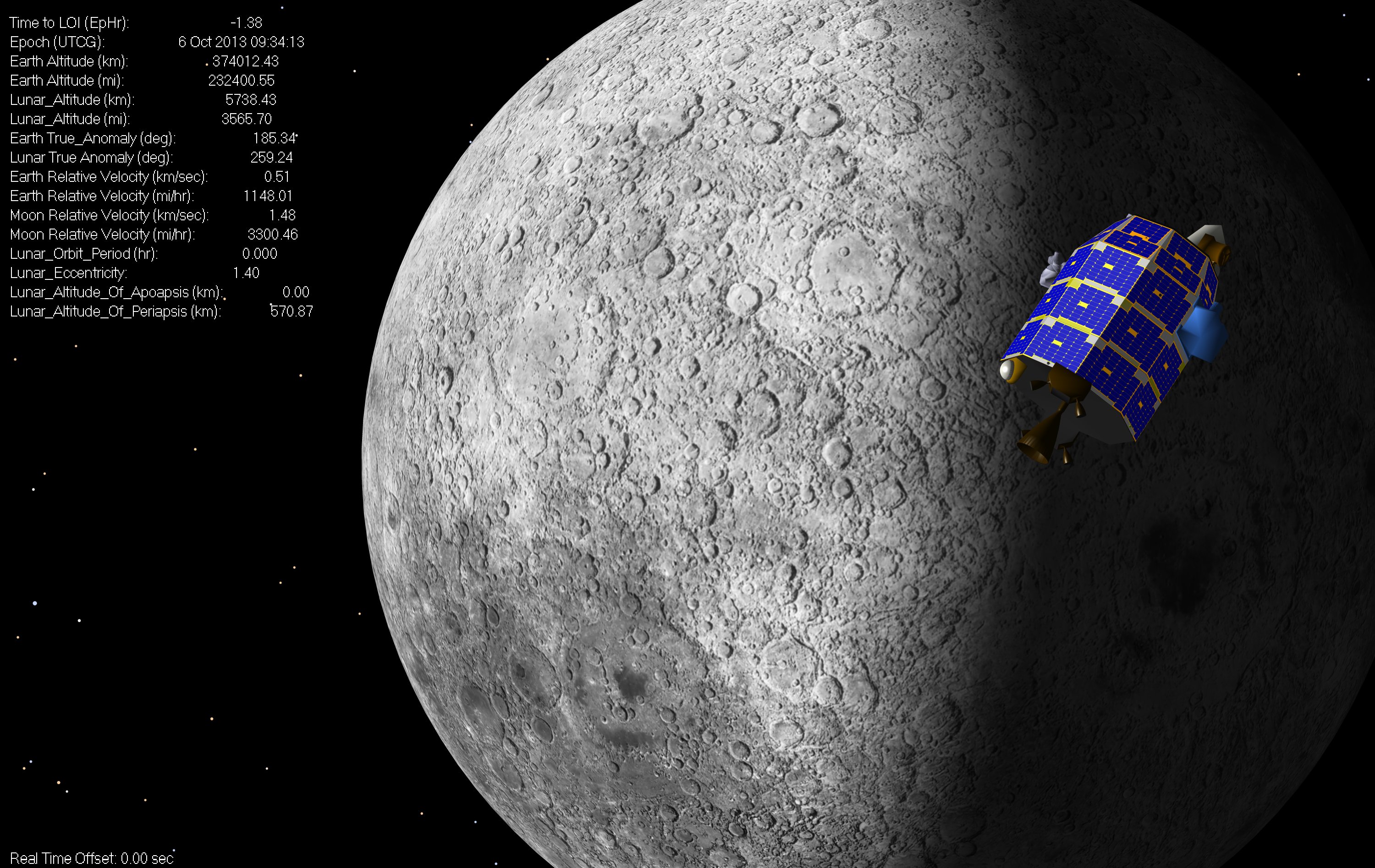
Note the last few parameters on the left. Lunar orbit period is zero (hyperbolic still), as is the Lunar Altitude of Apoapsis. The Lunar Altitude of periapsis isn’t accurate either, as the spacecraft is still mostly in Earth orbit. The Lunar disk is getting larger, and the Earth disk smaller:
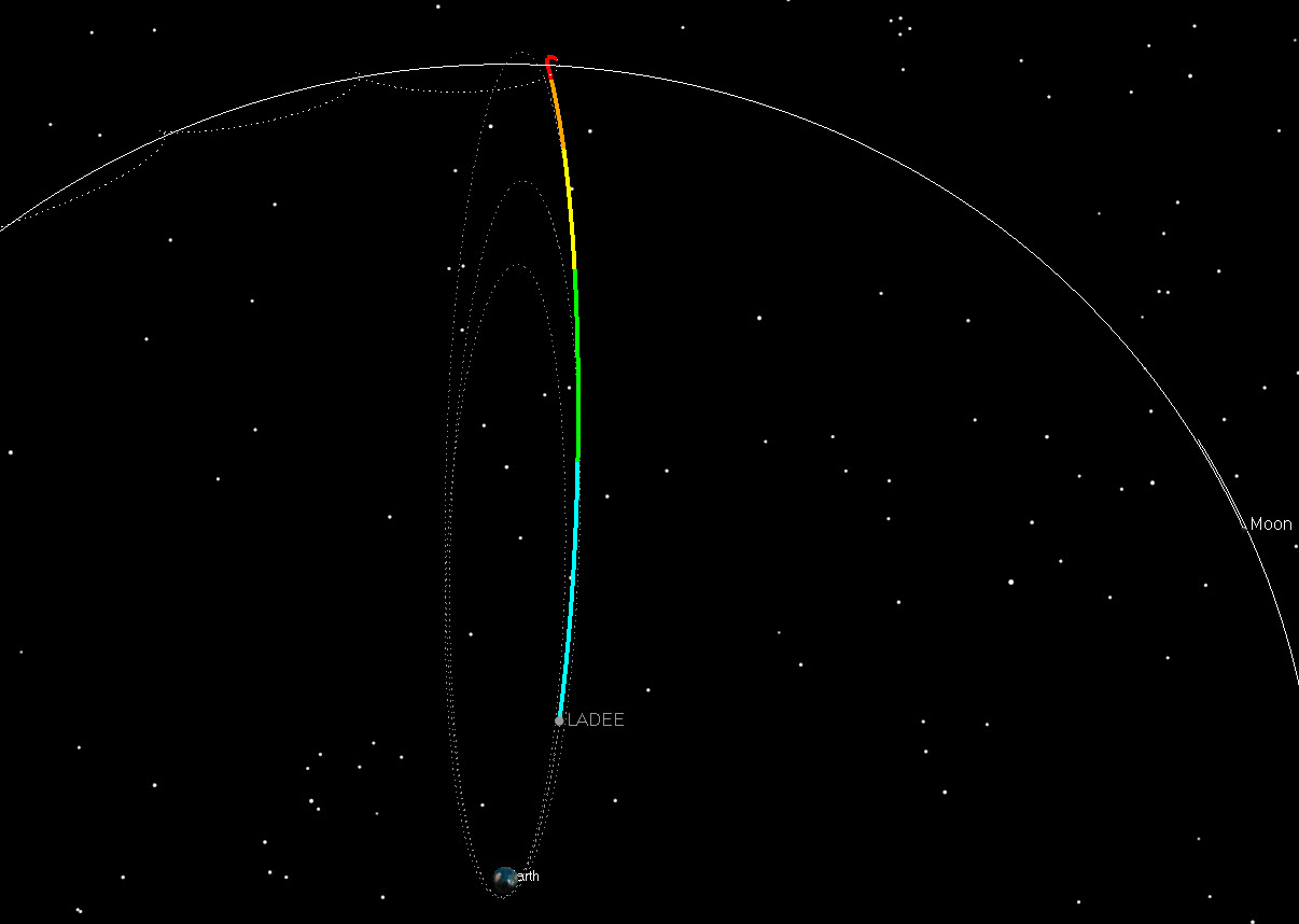
This shot shows the upcoming portion of the trajectory, when the Earth-bound trajectory is taken over by Lunar gravity:
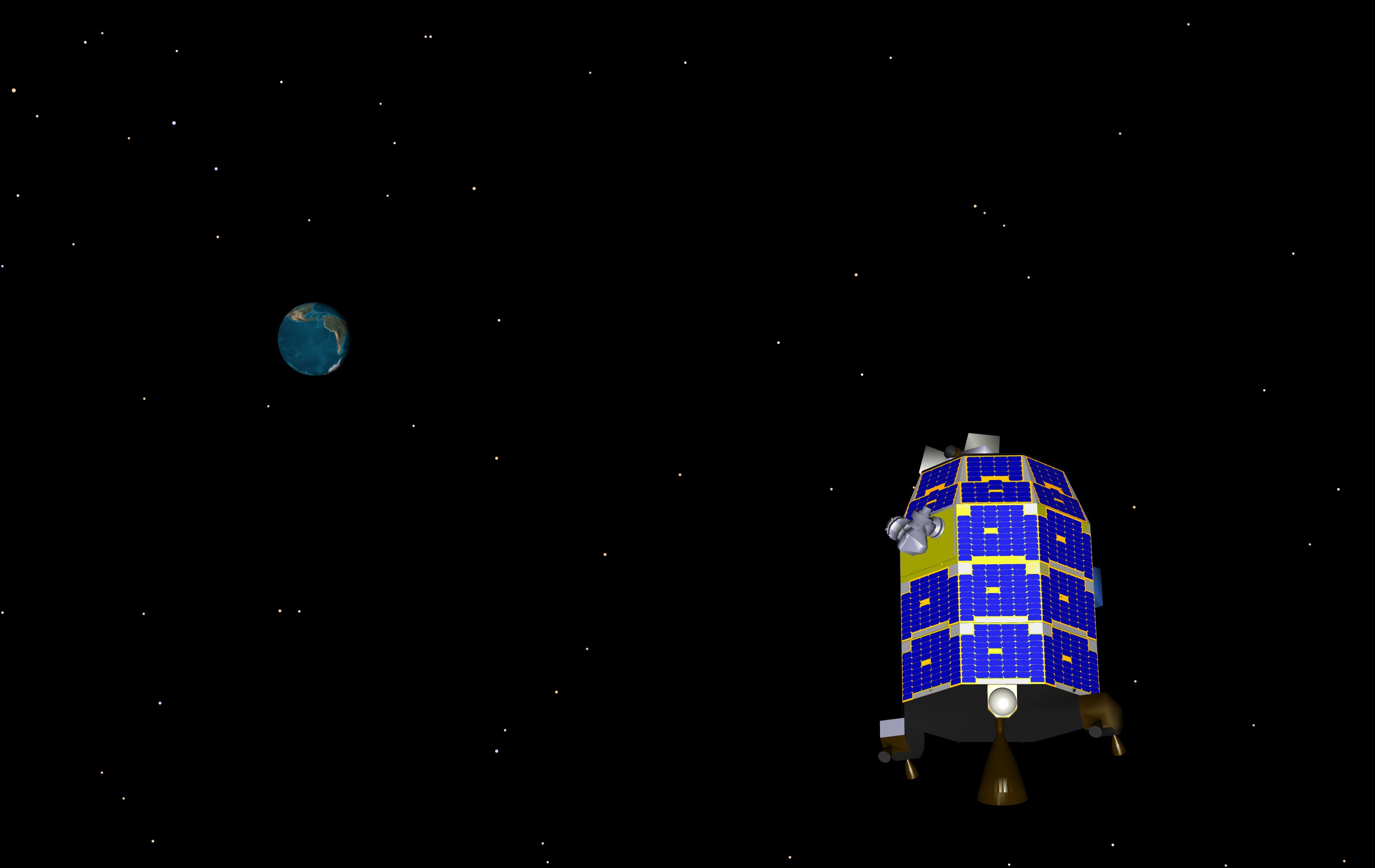
LADEE is rapidly approaching the Moon. Depending on who you talk to, you can consider the spacecraft to be within the “Sphere of Influence” of the Moon somewhere near 66,000 km (on LADEE we switch central bodies on our numerical integrators at 50,000 km, but that’s not a magic number). So we’re not quite Moon-Centered yet, but that doesn’t stop us from giving you pictures in a Moon centered frame.
As you can see, showing the Earth orbit no longer has great utility:
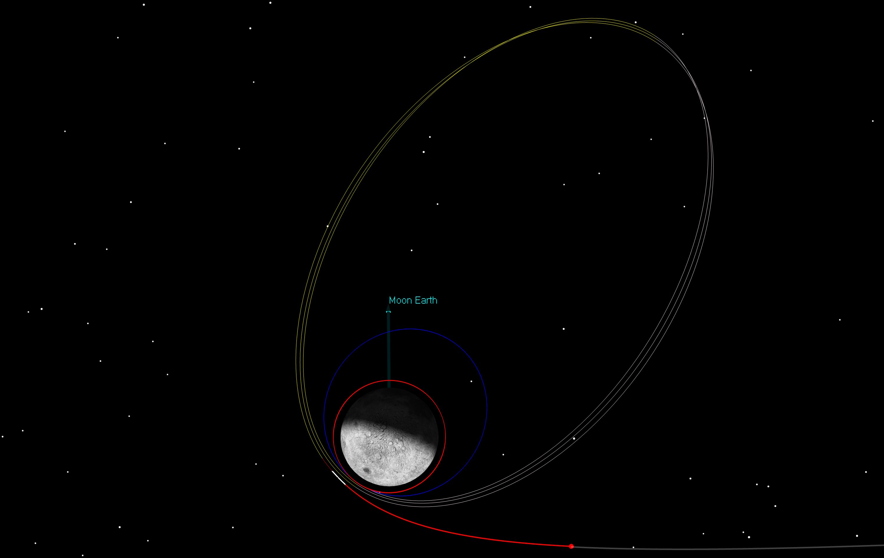
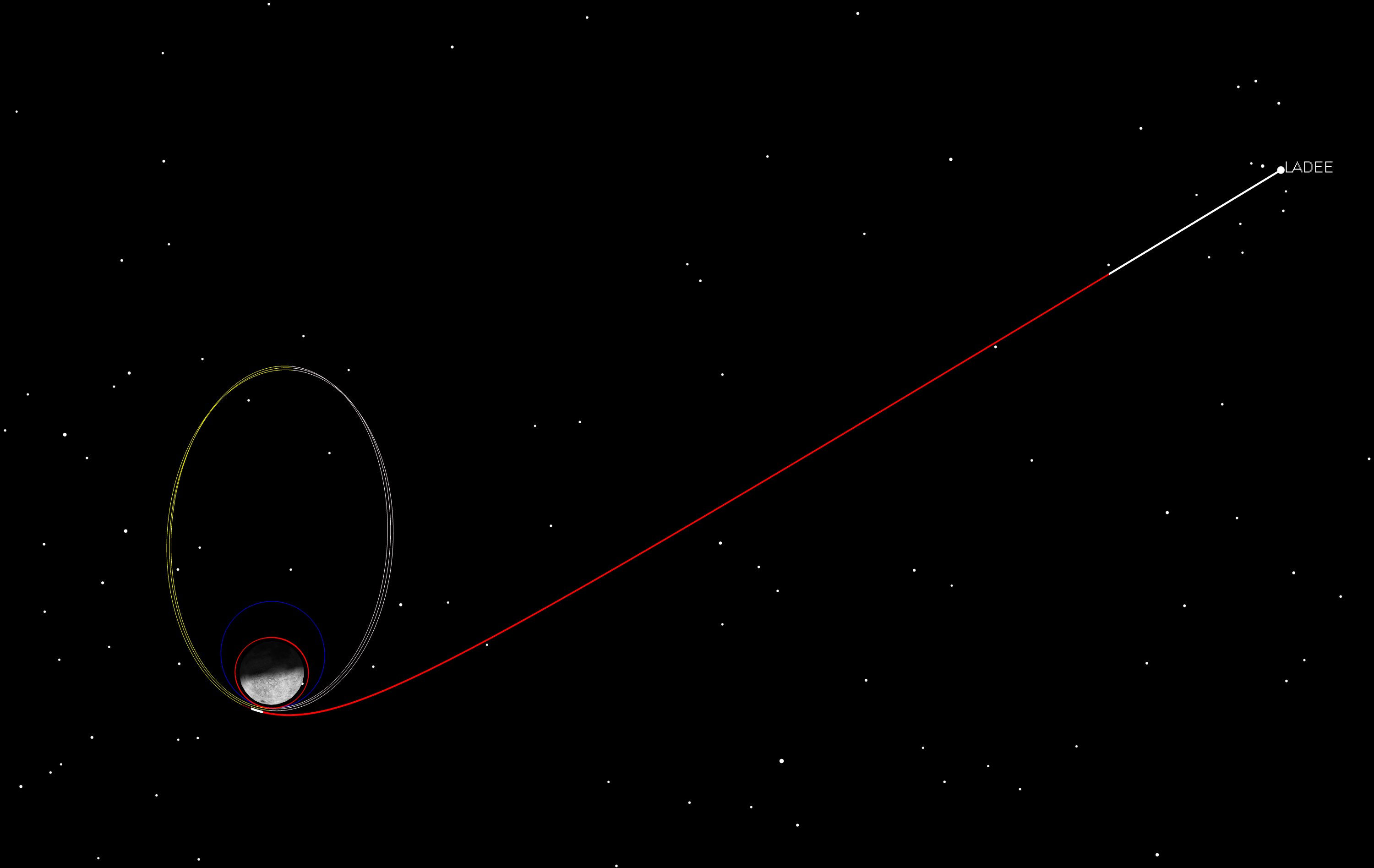
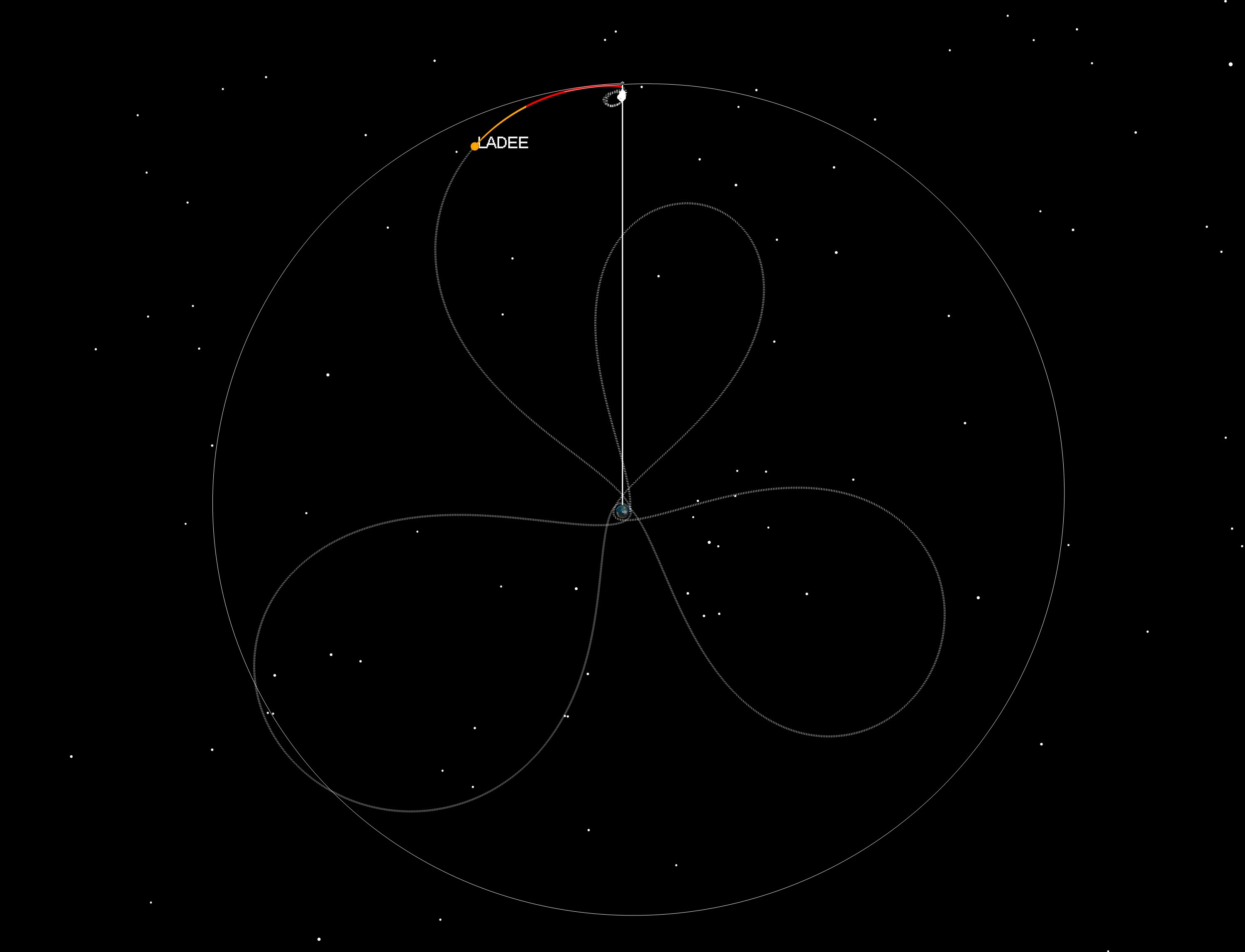
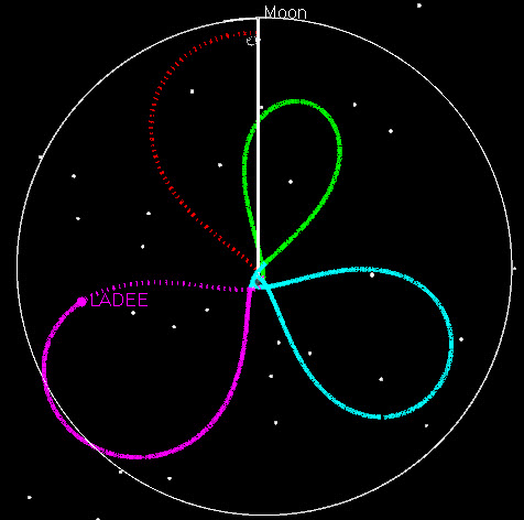
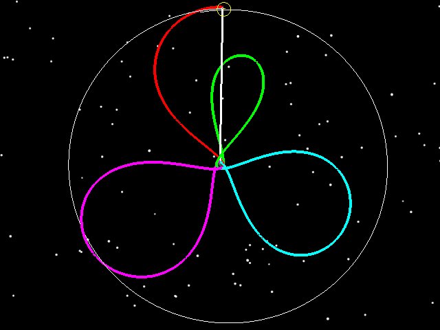
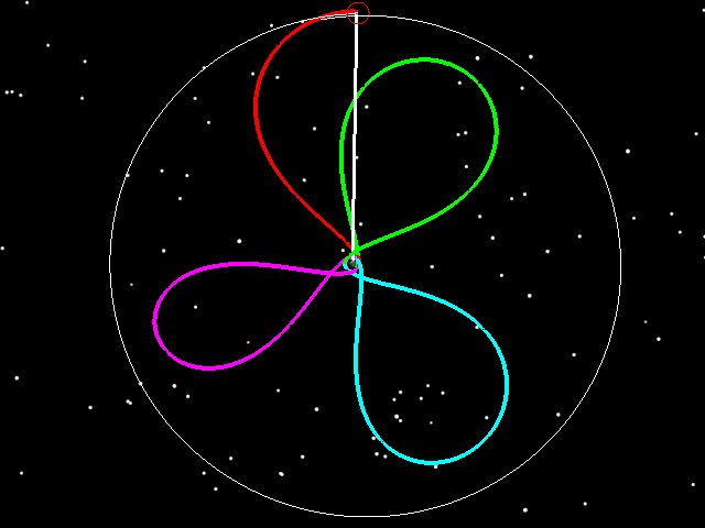
[Note: Velocity is still Earth-relative] I have to still show my favorite view of the phasing loops, the Earth-Moon rotating coordinate frame, but Earth-bound phasing loops are about to be less relevant.
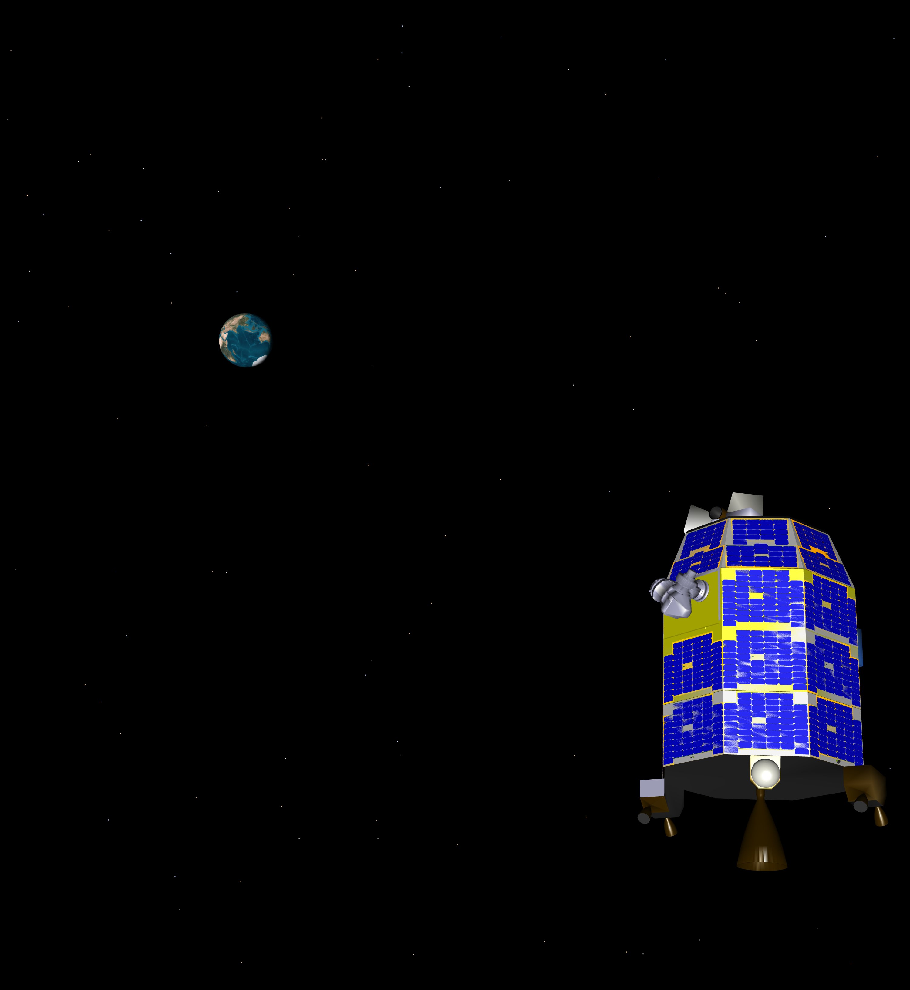
But as much as I like the phasing loops, this is the view we really should be thinking about (and I like it so much I just tweeted it!):
And this view gets me very excited:
But we still can look back to where we came from:
If you check the dates on the pictures, you can see what order I created them in, as the dates don’t all match and I’m animating in real time.
Today in the Flight Dynamics Room at Ames, fellow Astrogator Craig Nickel called out when LADEE became closer to the Moon than to the Earth – at 10:07 PDT tonight – and it’s not coming back!
LADEE on 10-1-2013 16:56 UTC (Earth-Centered Inertial View)
LADEE on 10-1-2013 16:56 UTC (Rotating Coordinate Frame)
LADEE on 10-1-2013 16:56 UTC (Top View)
LADEE passed perigee this morning near 4 AM PDT and is now headed for the Moon. Currently the spacecraft is above GEO, with the TCM-1 maneuver coming at 3 PM PDT today (1 Oct. 2013)
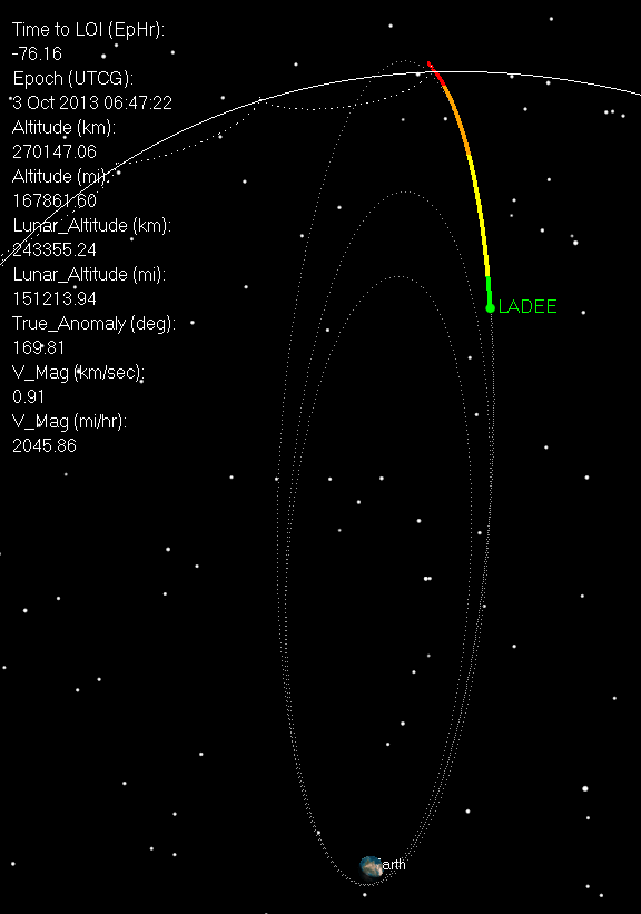
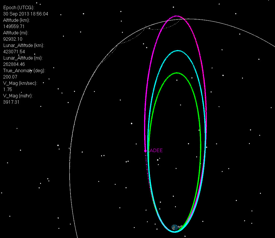
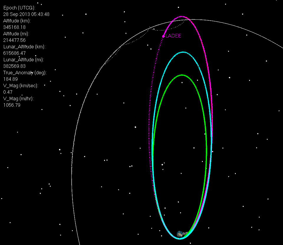
On Sep. 28 2013 05:33 UTC, LADEE is coming out of its last apogee and at an altitude of 214,000 km.
LADEE on 9-28-2013 5:46 UTC
LADEE on 9-28-2013 5:46 UTC (Top View)
Perigee occurs on 1 Oct near 11:00 UTC. A final small midcourse maneuver will take place at 1 Oct 2013, 22:00 UTC. This 0.9 m/sec maneuver will precisely target insertion parameters for the 6 Oct. 2013 10:57 UTC LOI-1 maneuver. LOI-1 is designed to place the spacecraft into a 24 hr orbit, with a periselene altitude of 590 km [correction: previously I said 750 km, this isn’t quite right. For LADEE we aren’t capturing right at periselene, like orbital mechanics would recommend. Instead we burn off periselene just a bit. We wait until 5 minutes past we come out from behind the Moon, and start our burn. This ends up being roughly 5.5 minutes after periselene. This allows the Deep Space Network to get a lock on us and telemetry to start flowing before the burn starts. So the altitude at the end of this burn is at about 750 km, but the actual periselene altitude is closer to 590 km]. After 3 revolutions in this orbit, 3rd-body Earth gravitational perturbations will have lowered periselene to an altitude of 250 km (by design). At this point, LOI-2 will be performed on 9 Oct 2013 10:37 UTC ( to place LADEE into a 4 hr orbit (also with a 250 km periselene altitude). LADEE will spend 3 days in this orbit until LOI-3 (12 Oct 2013 10:37 UTC), which circularizes the orbit at 250 km. LADEE will spend 30 days in this “commissioning orbit”, and will also perform tests using the laser communications experiment (LLCD). The timing and magnitudes of the maneuvers leading to the commissioning orbit are given below.
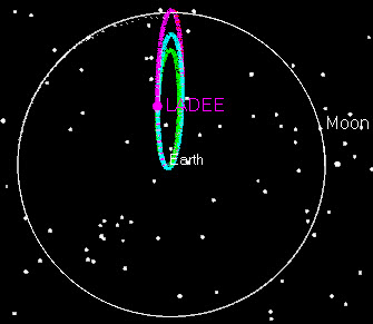
LADEE on 9-28-2013 5:48 (Earth-Moon rotating frame)
Executed Maneuvers:
AM1 11 Sep 2013 23:00:00.000 9.34 m/sec
PM1 13 Sep 2013 16:36:08.000 16.96 m/sec
PM2 21 Sep 2013 11:53:19.000 17.492 m/sec
Planned Maneuvers
TCM1 01 Oct 2013 22:00:00.000 0.9 m/sec
LOI1 06 Oct 2013 10:57:00.210 329.86 m/sec
LAM1 07 Oct 2013 22:51:32.205 0 m/sec (error corrections for LOI-1)
Here’s a quick LADEE update for Sept. 22, 2013. The LADEE team performed a second Perigee maneuver yesterday (21 Sep. 2013, 11:53 UTC) to raise LADEE’s orbit to have a period of 10 days, and to set up the spacecraft for Lunar capture on Oct. 6. LADEE’s path to this point is shown in dotted lines, while the upcoming trajectory is shown as solid. Note that LADEE is now in phasing loop 3, and will continue around a full orbit that will conclude on October 1st. LADEE will then begin the final portion of its trajectory, the 5 day trip to the Moon which concludes on Oct 6 with Lunar Orbit Insertion burn LOI-1. No further deterministic maneuvers are required (only a small TCM to correct out statistical errors from PM2) before the LOI phase begins. So even though LADEE has a full Earth orbit left, it is Moon-bound. LADEE is still in an elliptical orbit of the Earth, but at the next apogee LADEE will encounter the Moon.
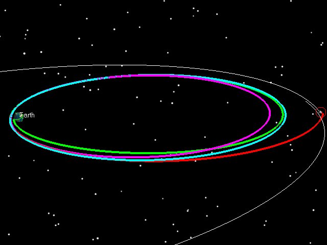
LADEE today in Earth-Moon Rotating Coordinate Frame
LADEE today in Earth-Centered Inertial Coordinate Frame
Many people have asked about LADEE’s trajectory, which uses 3 and a half “phasing loops” to get to the Moon. On one of my other postings, a reader asked if phasing loops saved delta-v on the trans-lunar injection (TLI) burn. The answer is no. The cost (in delta-v) to get to a lunar transfer from a specific injection orbit (for example the 6.4 day orbit LADEE currently is in) is the same if you go direct as it is if you go around a few times first.
The savings come elsewhere, in particular with the cost of correcting for errors from the launch vehicle (rocket).
There are four important reasons why phasing loops are being used for LADEE.
1. Mass
The Minotaur V couldn’t throw the whole mass of LADEE all the way to Lunar Injection.
2. Launch Dispersions
Let me borrow from my answer in the comments section on a previous post:
The Minotaur V, which is a stack of 5 solids, isn’t considered to be a particularly precise rocket. In other words, if we were to ask for a 6.3 day orbit, we might get a 5 day orbit, or we might get an 8 day orbit. In a direct injection trajectory (such as the 3-day missions used by Apollo), injection errors can only be corrected out after good amount of tracking can be done (~ 24 hrs normally) to determine the orbit (OD, or “Orbit Determination”). However, as the spacecraft gets further and further away from the Earth, the cost of correcting out launch errors gets larger as well. Often times, by the time enough tracking data can be gathered, the cost of correcting out any launch errors can be 5-10 times the actual size of the error. So a 5 m/sec error would take 25 m/sec to correct, etc.
If, instead of using a direct approach, you use phasing loops the cost is a lot closer to 1:1 (i.e. a 5 m/sec error in launch costs 5 m/sec to correct, or can even save you fuel). It’s not a pure 1:1 ratio, because there is a timing aspect as well, but in terms of the energy of the orbits, it is 1:1.
Assume that you’re going to launch to a 6.4 day orbit and that you’ll then transfer to an 7.6 day orbit, and then a 10 day orbit, and then spend 5 days getting to the Moon (total of 29 days). The cost of transferring to the 5-day lunar transfer from the 6.4 day starting orbit is always the same. Now say that your rocket doesn’t give you exactly what you want, and instead of a 6.4 day orbit, you are inserted into a 7 day orbit. Instead of doing a TCM to correct out that error, you simply replan your trajectory profile. You spend 7 days in the first orbit, but instead of transferring to a 7.6 day orbit, your first maneuver is zero, and you stay in the 7 day orbit for 2 days. So your first rev is 7 days, second rev is 7 days, and then you transfer to a 10 day orbit, and take 5 more to get to the Moon (still 29).
Same thing if you are launched to a 5 day orbit. The second orbit can be 9 days, the third 10, and 5 days to the Moon (29 days total again).
You get the picture.
The total delta-v to get to the Moon doesn’t really change, but your orbit profile is flexible to large dispersions in your injection.
Phasing loops have been used on many other missions (Clementine and WMAP are 2 good examples). I designed the phasing loops on LADEE to accommodate the Minotaur V dispersions. The LADEE spacecraft barely had enough fuel to do its science mission, and the choice of phasing loops allowed the mission to accommodate the Minotaur V dispersions, at the cost of some extra time in cislunar space. The operations costs are not free (of course), but if you can’t fit on the rocket, sometimes you don’t have a mission.
[Funny thing is that although the Minotaur V is “supposed” to have large dispersions, the fact is that the launch last Friday (Sept 7, 2013) was just about perfect. We got almost precisely the nominal trajectory, in what probably is the most precise injection a Minotaur rocket has ever done. Had we known in advance that we could have gotten such an injection, we probably would have gone direct.]
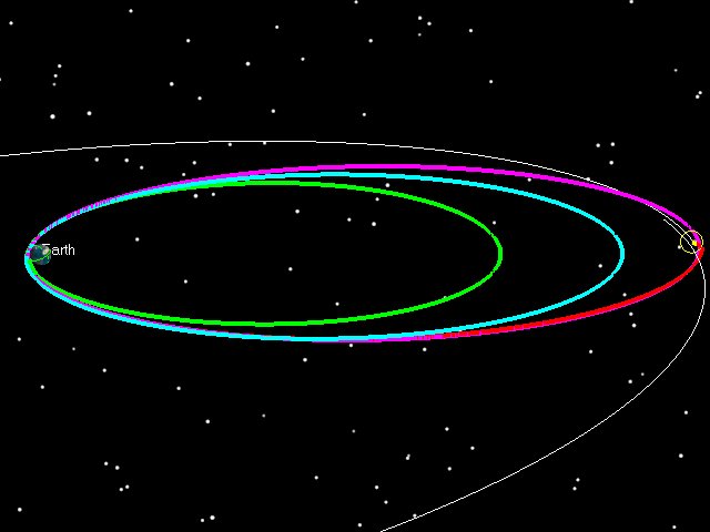
So here are a few examples of how phasing loops allow you flexibility. As stated previously, LADEE was launched into a 6.4 day orbit. However, let’s say LADEE got into a 5 Day orbit instead:
If LADEE had been launched into a 5 day orbit (green), we then could have raised the 2nd orbit to have a 9.5 day period (blue), and the third to have a 9.8 day period purple and then done our normal 5 day transfer to the Moon. The two pictures below tell the story. On the left the orbit is shown in an Earth-Moon Rotating coordinate system. The Earth is in the middle, and the Moon is stationary from the top. Imagine that you’re way above the Earth-Moon system, and that you are slowly rotating at exactly the same rate as the Moon goes around the Earth. On the right is the normal view, an Earth-centered inertial frame.
5 Day Insertion Orbit, Earth-Moon Rotating Coordinate Frame
5 Day Insertion Orbit, Earth-Centered Inertial Coordinate Frame
If LADEE had been launched into a 6 day orbit (green), we then could have raised the 2nd orbit to have an 8.3 day period (blue), and the third to have a 9.9 day period purple and then done our normal 5 day transfer to the Moon.
6 Day Insertion Orbit, Earth-Moon Rotating Coordinate Frame
6 Day Insertion Orbit, Earth-Centered Inertial Coordinate Frame
If LADEE had been launched into a 7 day orbit (green), we then could have raised the 2nd orbit to have an 8.1 day period (blue), and the third to have a 9 day period purple and then done our normal 5 day transfer to the Moon.
7 Day Insertion Orbit, Earth-Moon Rotating Coordinate Frame
7 Day Insertion Orbit, Earth-Centered Inertial Coordinate Frame
If LADEE had been launched into an 8 day orbit (green), we then could have raised the 2nd orbit to have an 8.4 day period (blue), lowered the third to have a 7.7 day period purple and then done our normal 5 day transfer to the Moon. The 8 day orbit and above starts to cost more energy, because you have to lower the 2nd orbit and then raise it back up for the third. So in this case, while the rocket would have placed us in a higher orbit than we wanted (and thus you’d think it might save us energy) we end up having to pay a bit extra to get the timing right.
8 Day Insertion Orbit, Earth-Moon Rotating Coordinate Frame
8 Day Insertion Orbit, Earth-Centered Inertial Coordinate Frame
Note here that all the examples I show have us keeping the time of the third perigee mostly constant, along with the time of flight between that perigee and the Moon constant at 5 days. This comes from the fact that once we’ve launched and the Minotaur Stage 5 has fired, our line of apsides (between apogee and perigee) is mostly fixed in space (actually it was fixed before launch for optimization purposes, but that’s another topic) and we are now locked into getting at the Moon when the Moon is at the same latitude as our apogee.
3. Widening the Launch Window
Another thing phasing loops give you are a wider launch window. With the argument of perigee (and thus the line of apsides) fixed before launch, we are fixed to arrive at the Moon when it as a specific latitude (same as our apogee). Given that, a direct launch would have only had a very short launch period if you assume that you’re always launching with the same energy from the upper stage. Phasing loops allow you to widen the window up to 5 days. In the case of LADEE, we actually launched on the first day of the launch period (on the first second of the launch window) but we were lucky. We’ll take the luck, but we didn’t plan for it. Instead, we had a 5 day window.
On the first day of the launch window (Sep. 6, 2013), our first orbit would be 6.4 days, the 2nd 7.95, the third 9.95 and then about 5 days to the Moon.
Day 1 of Launch period, Earth-Moon Rotating Coordinate Frame
Day 1 of Launch Period, Earth-Centered Inertial Coordinate Frame
On the second day of the launch window (Sep. 7, 2013), our first orbit would be 6.33 days [Note: the rocket is always launching us to the same orbit, but the Moon’s gravity alters our orbit a bit, so the first rev doesn’t always have the same period] , the 2nd 7.00, the third 9.95 and then about 5 days to the Moon.
Day 2 of Launch Period, Earth-Centered Inertial Coordinate Frame
Day 2 of Launch Period , Earth-Moon rotating Coordinate Frame
On the third day of the launch window (Sep. 8, 2013), our first orbit would be 6.24 days, the 2nd 6.32, the third 9.55 and then about 5 days to the Moon.
Day 3 of Launch Period, Earth-Moon Rotating Coordinate Frame
Day 3 of Launch Period, Earth-Centered Inertial Coordinate Frame
On the fourth day of the launch window (Sep. 9, 2013), our first orbit would be 6.19 days, the 2nd 6.27, the third 8.82 and then about 5 days to the Moon.
Day 4 of Launch Period, Earth-Moon Rotating Coordinate Frame
Day 4 of Launch Period, Earth-Centered Inertial Coordinate Frame
The last day of the launch window (Sep. 10, 2013), our first orbit would be 6.16 days, the 2nd 6.32, the third 7.95 and then about 5 days to the Moon.
Day 5 of Launch Period, Earth-Moon Rotating Coordinate Frame
Day 5 of Launch Period, Earth-Centered Inertial Coordinate Frame
Why does the launch period stop? Look at the rotating frame picture in each of the examples. Think of the picture in terms of quadrants, with the first quadrant being in the upper right, second in the lower right, third in the lower left, and 4th in the upper left. Any loop in the first quadrant gets to apogee with the Moon in front of it. This is fine, because the gravity of the Moon will give us some extra velocity at apogee, and will raise our subsequent perigee altitude. The closer we are to the Earth-Moon line (the vertical white line in the rotating frame picture), the more boost we get from the Moon. The further away we are from the Moon, the less boost we get. Going into the 4th quadrant is bad, because if we get in front of the Moon at apogee, then the Moon’s gravity slows us down, and drives the perigee altitude into the Earth. In the 2nd quadrant we get slight gravitational lowering at perigee, and the 3rd we get slight gravitational raising. If you watch the sequence through the launch period, you see that each day the first loop clocks further (clockwise) to the right, closer to the 2nd quadrant. We have to launch to get our orbital plane to match the Moon’s on arrival, and also have to make this happen when the Moon has the same latitude as our apogee.
This is all important for the trajectory planning of LADEE, because when you launch off a rocket from the Earth, your insertion perigee is usually low (200 km). You don’t want to come back at this altitude the next time around. So we launch when the Moon will raise us (without requiring a maneuver at apogee, which we could also do, but we’d rather not require a maneuver at the first apogee to keep the spacecraft from hitting the Earth). So as long as our first loop stays within the first quadrant in the rotating frame, we’re OK. This gives us a 4-5 day launch window (some times we lose the first day if we decide that potential launch dispersions will throw too many statistical cases into the 4th quadrant.)
4. Flexibility after launch
The phasing loop plan is also very robust in the face of missed maneuvers. A missed PM1, for example, can easily be accommodated by modified PM2 and PM3 maneuvers and still get to the Moon at the same time. A missed PM2 is can be accommodated by waiting another month in orbit, and achieving LOI-1 in November. The ability of the plan to easily be modified in the face of contingencies is another strong feature of the phasing orbit approach.
In the pictures below, we see what happens with a missed PM1. The spacecraft stays in 6.4 day orbit for a second rev, and then raises to a 11.25 day orbit with a 41 m/sec maneuver. At the final perigee (Pf or PM3) we execute a -8 m/sec maneuver to bring apogee down to Lunar altitude.
Post Launch Missed PM1 Trajectory, Earth-Moon Rotating Coordinate Frame
Post Launch Missed PM1 Trajectory, Earth-Centered Inertial Coordinate Frame
The plan is also robust to a missed PM2 maneuver. This profile would require LADEE to wait an extra month in Earth orbit. The gray orbits indicate the first month. We show the trajectory starting after PM1 moving towards PM2. Once PM2 is missed, the spacecraft spends 2 more revs in the grey (moving through the 4th quadrant) and then the approach pattern starts again.
Post Launch Missed PM2 Trajectory, Earth-Moon Rotating Coordinate Frame
Post Launch Missed PM2 Trajectory, Earth-Centered Inertial Coordinate Frame
Phasing loops offer several advantages to the mission planner. At the expense of longer operation costs, phasing loops have offer a reduced TCM budget in the face of large launch dispersions, expanded launch windows, and over-all robustness to contingencies.
To provide the best experiences, we use technologies like cookies to store and/or access device information. Consenting to these technologies will allow us to process data such as browsing behavior or unique IDs on this site. Not consenting or withdrawing consent, may adversely affect certain features and functions.
Functional
Always active
The technical storage or access is strictly necessary for the legitimate purpose of enabling the use of a specific service explicitly requested by the subscriber or user, or for the sole purpose of carrying out the transmission of a communication over an electronic communications network.
Preferences
The technical storage or access is necessary for the legitimate purpose of storing preferences that are not requested by the subscriber or user.
Statistics
The technical storage or access that is used exclusively for statistical purposes.The technical storage or access that is used exclusively for anonymous statistical purposes. Without a subpoena, voluntary compliance on the part of your Internet Service Provider, or additional records from a third party, information stored or retrieved for this purpose alone cannot usually be used to identify you.
Marketing
The technical storage or access is required to create user profiles to send advertising, or to track the user on a website or across several websites for similar marketing purposes.

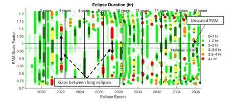
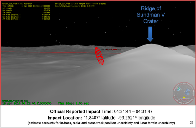
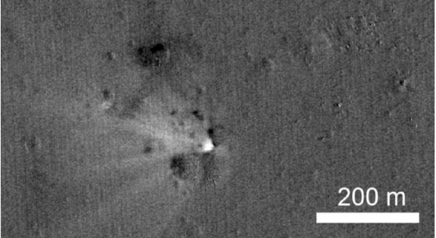
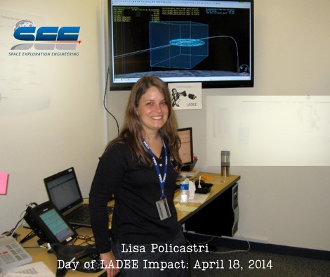
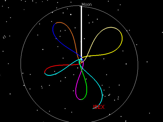
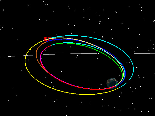
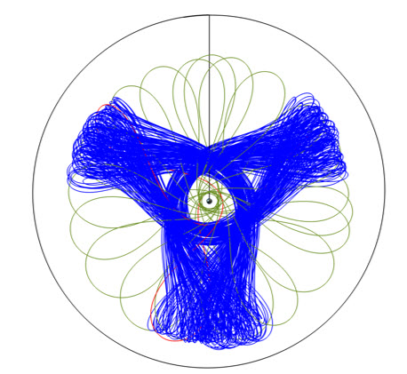
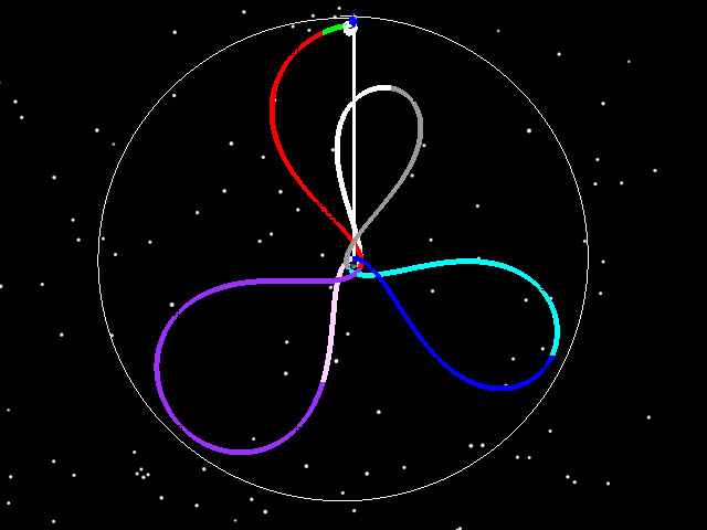
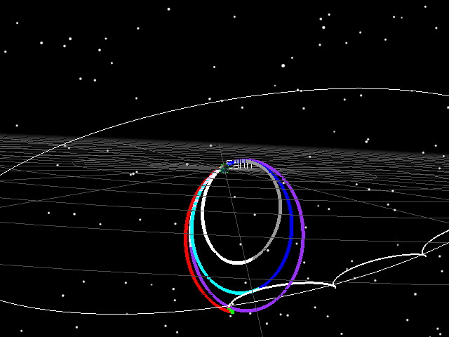
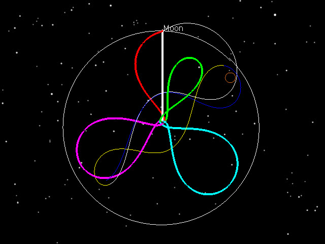
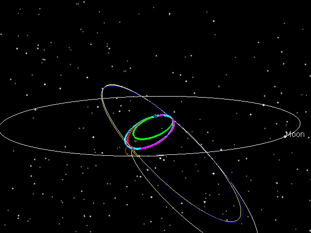
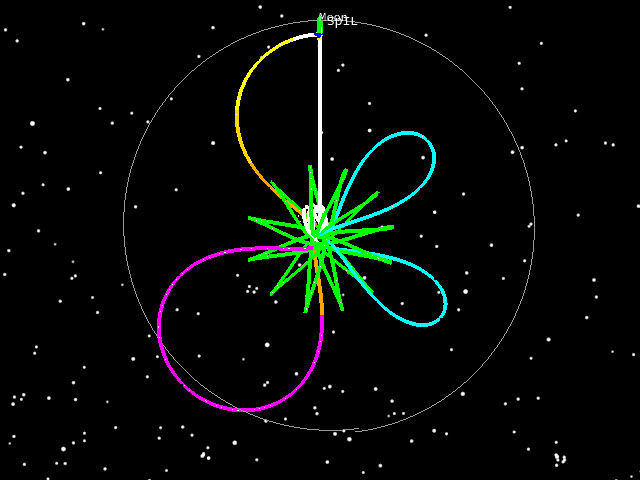
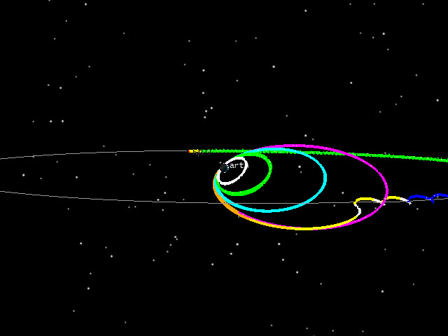
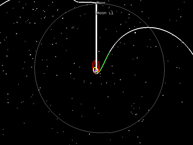
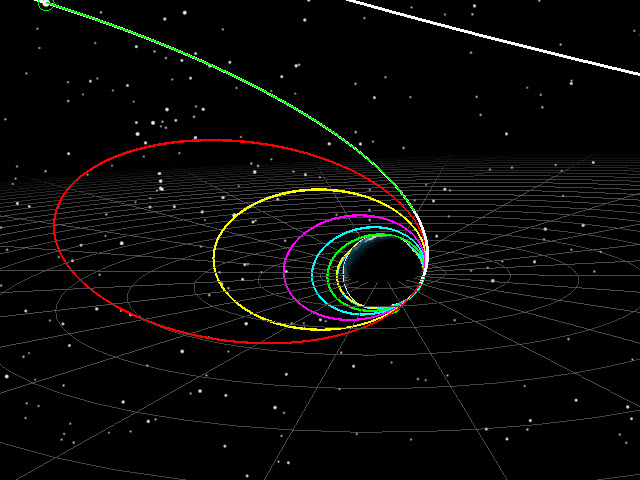
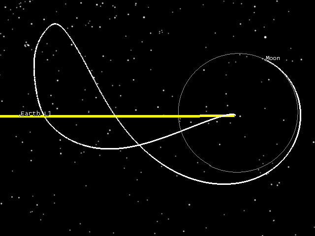
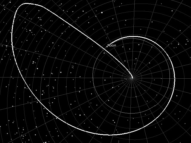

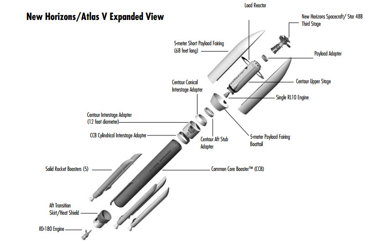
![New Horizons Atlas 551 (5 meter fairing, 5 solids, 1 RL10 on the Centaur) [Click to enlarge]](https://astrogatorsguild.com/wp-content/uploads/2015/07/NewHorizons_Rocket_Bly.jpg)
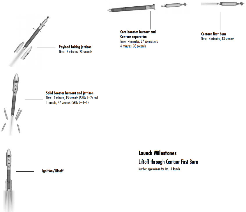

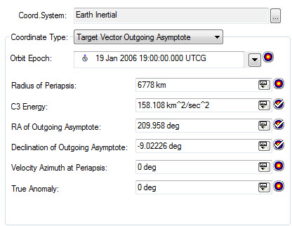
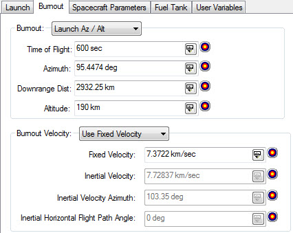
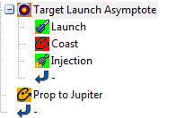
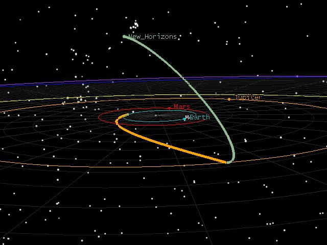
![New Horizons Jupiter Flyby (from Yanping's paper sited earlier) [Click to Enlarge]](https://astrogatorsguild.com/wp-content/uploads/2015/07/yanping-flyby-geometry.jpg)
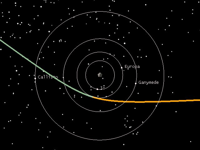

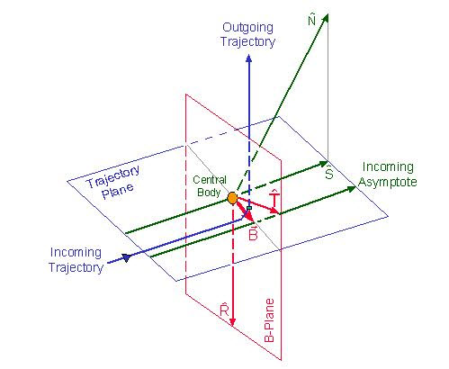
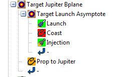
![New Horizons Trajectory with Jupiter Bplane Targeting [Click to Enlarge]](https://astrogatorsguild.com/wp-content/uploads/2015/07/bplane_target2.jpg)