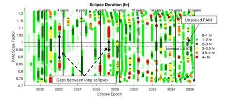
Six years ago, on May 30th 2018, the TESS spacecraft executed a Period Adjust Maneuver (PAM) to insert the spacecraft into its final 2:1 Lunar Resonant mission orbit. This concluded a series of maneuvers after launch on a SpaceX Falcon 9 that targeted a Lunar flyby to swing the orbit plane out of the ecliptic plane and avoid long duration eclipses for more than 18 years.
Missions like TESS have the potential to return valuable science for decades, as long as the spacecraft can survive. Careful mission design can greatly increase the chances of mission survival beyond primary mission completion. The 2:1 resonance of the TESS orbit removed any need for orbit station keeping, allowing for long-term prediction of eclipse durations. Monte Carlo analysis during operations then enabled the flight dynamics team to actively target PAM to avoid any that could be mission-ending.
TESS is now in its second extended mission after 6 highly-productive years of exoplanet discovery! SEE’s Ryan Lebois and Craig Nickel supported NASA Goddard Space Flight Center (GSFC) during the mission design and operations of TESS through successful mission orbit insertion.
Learn More
Read Ryan Lebois and Craig Nickel’s conference paper to learn more.
April 18th marks 10 years since the NASA LADEE mission successfully ended with an impact to the lunar surface! The NASA Ames Research Center (ARC) led this mission, which carried three instrument payloads and one tech demo – the Lunar Laser Communications Demonstration. The mission operated successfully through its planned science phase of 100 days and an extended mission phase of 45 days, with the last few weeks spent operating at an extremely low altitude to enhance science collection.
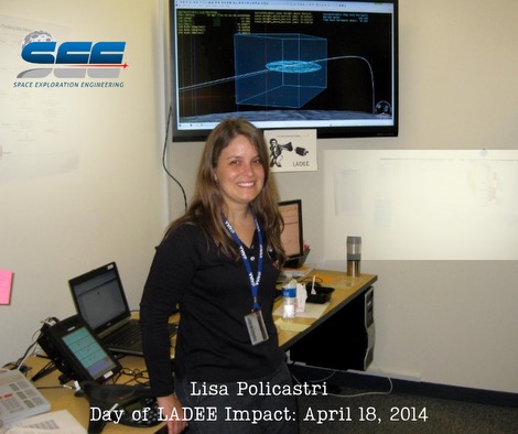
SEE’s Lisa Policastri served as the Orbit Determination Lead throughout all phases of mission development and mission operations, including during the final shift on console at the ARC multi-mission operations center when LADEE impacted the Moon at the Sundman V crater rim at a velocity of 3,600 miles per hour.
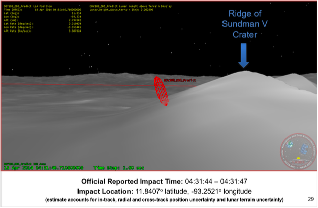
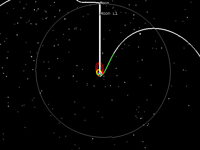
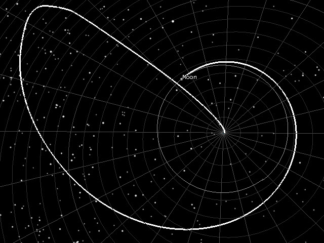
The image below, from our 2014 archives, shows our model of LADEE’s position in orbit (red line) with the uncertainty model (red ellipsoid) just before impact at the Sundman V Crater ridge on this day 10 years ago.
This image from our 2014 archives depicts our model of LADEE’s orbit (red line), along with the uncertainty model (red ellipsoid), just before impact at the Sundman V Crater ridge, exactly 10 years ago today.
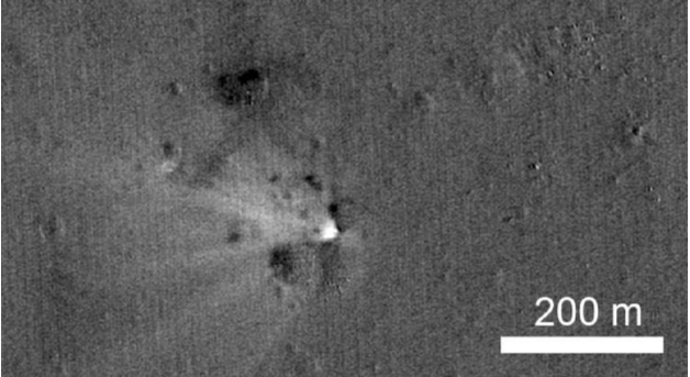
Later in 2014, the Lunar Reconnaissance Orbiter Camera confirmed the location of LADEE’s impact.
This shows LADDEE’s impact site, near the Sundman V Crater.
This video shows the last orbit of LADEE up to impact.
NASA’s 2014 article titled “NASA’s LRO Spacecraft Captures Images of LADEE’s Impact Crater” states, ” ‘The Lunar Reconnaissance Orbiter Camera (LROC) team recently developed a new computer tool to search Narrow Angle Camera (NAC) before and after image pairs for new craters, the LADEE impact event provided a fun test,’ said Mark Robinson, LROC principal investigator from Arizona State University in Tempe. ‘As it turns there were several small surface changes found in the predicted area of the impact, the biggest and most distinctive was within 968 feet (295 meters) of the spot estimated by the LADEE operations team. What fun!’ ”
In addition to Lisa, many current SEE team members were heavily involved in the LADEE mission’s success, including Mike Loucks, John Carrico, Craig Nickel, Alisa Hawkins, and Ryan Lebois. The entire LADEE mission operations team was a truly amazing group! No one slept much during those final days – everyone relied on strong teamwork and lots of caffeine and snacks!
Lisa Policastri on the Day of the LADEE Impact: April 18, 2014
Today we have been reflecting on an impactful experience that happened on this day, March 14th, in 2008!
After a failure of its Briz-M upper stage shortly after launch on March 14, 2008, the AMC-14 communications satellite was left stranded in an inclined geostationary transfer orbit. John Carrico and Mike Loucks developed a recovery trajectory to deliver the spacecraft to its originally intended orbit.
Changing the angle between a spacecraft’s orbit plane and the equator is expensive in terms of propellant. Since AMC-14 was stranded near an inclination of 52 degrees, propellant could be conserved by boosting the apogee of the spacecraft’s orbit out to lunar distance.
Two lunar encounters (a “double lunar swingby”) reduced the inclination to 0 degrees (an equatorial orbit) and raised perigee to GEO altitude. Perhaps counterintuitively, the propellant required for these large changes in altitude was less than that required to reduce inclination propulsively.
Ultimately, AMC-14 did not utilize a double-lunar swingby trajectory to reach GEO. Instead, a series of low-thrust maneuvers were performed to raise orbit and eventually reach an inclined, geosynchronous orbit.
Double lunar swingbys are one of the “tools” in the astrogator’s toolbox. For resource constrained missions, lunar gravity assists can enable large orbit changes while conserving propellant. Every day, the SEE team applies techniques like this to solve challenging mission design problems!
30 years ago yesterday, the Deep Space Program Science Experiment spacecraft, dubbed “Clementine,” entered lunar orbit after executing the Lunar Orbit Insertion (LOI) maneuver to place it into a 426.9 km x 5485.1 km orbit, with an orbit period of 8 hours.
Originally launched on a Titan II(23)G rocket from Vandenberg Air force Base launch site SLC-4W on January 25, 1994, the spacecraft used an R-4D 490 Newton engine to perform the insertion. The R4D used bipropellant hydrazine (N2O4/MMH) with an Isp of 310 sec.
The LOI maneuver was planned using the software tool “Swingby” at Goddard Space Flight Center. SEE founder, Astrogator John Carrico, was on the team that both developed Swingby and used it for maneuver planning on the Clementine mission. Swingby eventually evolved into the STK/Astrogator trajectory planning tool.
Learn More
To learn more read Lawrence Livermore National Laboratory’s article, “The Clementine Satellite.”
Dr. Worden was Director of NASA Ames during both the Lunar Crater Observation and Sensing Satellite (LCROSS) and Lunar Atmosphere and Dust Environment Explorer (LADEE) Missions. LCROSS launched in 2009. LADEE launched in 2013. The SEE team supported both of these missions.
30 years ago today, the Deep Space Program Science Experiment, dubbed “Clementine,” ignited its Star-37FM solid rocket motor to leave low Earth orbit and embark on a 2.5 phasing loop trajectory to lunar orbit. SEE’s CTO, Astrogator John Carrico, was in the frozen flight dynamics facility at NASA’s Goddard Spaceflight Center, keeping a watchful eye on the spacecraft’s trajectory. Clementine returned the United States to lunar orbit after a two-decade absence and ignited a new era of lunar exploration.
Clementine was developed as a unique Department of Defense program to demonstrate dual-use technology in deep space. The mission went from inception to launch in about 22 months for a total cost of $75M. The Naval Research Laboratory designed, built, and operated the spacecraft, turning to the Flight Dynamics Division at NASA Goddard for support during the critical lunar transfer and orbit insertion phases of the mission.
At NASA Goddard, John Carrico was on the team developing Swingby, a trajectory design application tailored for multi-gravitational trajectories. While previously employed for pre-launch analyses on other deep space missions, Clementine was Swingby’s opportunity to support operational trajectory planning and re-design. When a battery anomaly threatened to strand Clementine in LEO, Swingby proved its worth. It enabled the flight dynamics team to deliver over 50 maneuver plans over a span of 8.5 days, often with as little as 12 hours lead time.
Eventually, Swingby evolved into the highly capable Astrogator trajectory planning tool included in AGI STK. The phasing loop lunar transfer pioneered by Clementine enabled subsequent small lunar missions, like NASA’s Lunar Atmosphere and Dust Environment Explorer, SpaceIL’s Beresheet, and Astrobotic’s Peregrine lunar lander. Science data returned by Clementine indicated the presence of water ice at the Moon’s South Pole.
Join all of us here at The Astrogator’s Guild as we celebrate the 30 year anniversary of Clementine’s journey to the Moon and look forward to the next 30 years of bold, inspiring lunar exploration.
When Rocket Lab’s Electron rocket launches the CAPSTONE spacecraft, it will use a series of precisely targeted orbit raising maneuvers and phasing orbits in low Earth orbit to achieve the final injection conditions required to achieve the Ballistic Lunar Transfer that CAPSTONE requires. These maneuvers will be executed by Rocket Lab’s updated “Photon” stage and the plan for these maneuvers will be developed by Rocket Lab’s flight dynamics team. The Rocket Lab Flight Dynamics (FIDO) team consists of Space Exploration Engineering (SEE) and Rocket Lab FIDO engineers who have been training with SEE over the last 2 years. SEE brings a wealth of experience in planning and executing cislunar trajectories of just this type. A big part of our business model is to bring this expertise to our customers so they can continue do these types of projects when the mission is over.
The expertise of SEE’s team comes from missions such as Clementine (DSPSE) which flew in 1994, ISTP(1994), WMAP(2001), IBEX(2008), LCROSS(2009), LADEE(2013), TESS(2018) and SpaceIL Beresheet(2019). All of these missions used combinations of precisely timed Earth phasing orbits and orbit raising maneuvers to achieve their objectives, just as Photon will do to inject the CAPSTONE onto its desired deep space asymptote.
The CAPSTONE Earth orbit profile builds directly from SEE trajectory design and operational experience from a number of previous missions. Each mission design comes from a series of requirements imposed by the launch vehicle (how much mass it can lift to what orbit), the spacecraft propulsion system (how long can burns be, and how many can be done), the navigation techniques used (how many ground passes needed, how big are the antenna on the ground) and operations (how much time does it take to generate new burn plans, process tracking data, generate and test new command files, etc.).
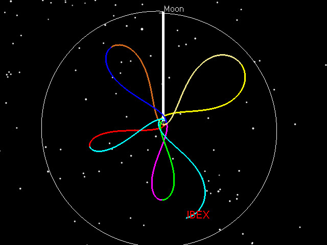
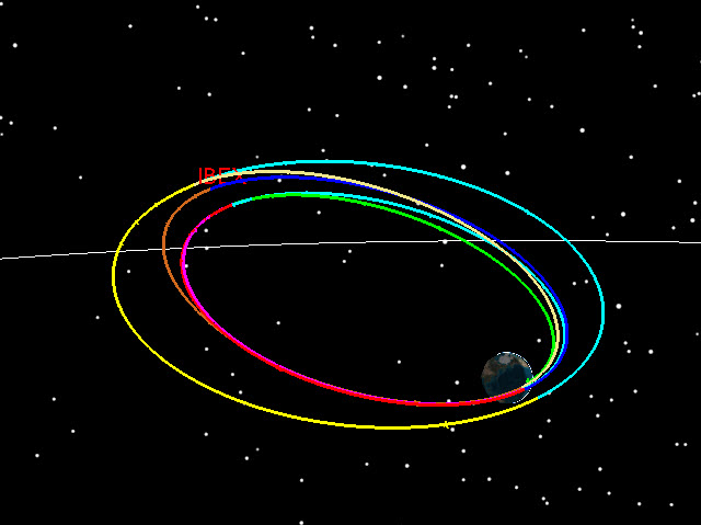
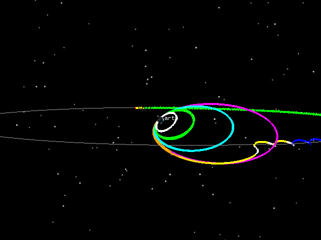
The Interstellar Boundary Explorer (IBEX) trajectory plan was designed, navigated and executed by SEE personnel in 2008. Figure 1 shows the trajectory in an Earth-Moon rotating frame. IBEX used 4 phasing orbits (or loops) to precisely insert IBEX on the desired trajectory in cislunar space. This orbit was ultimately modified to be a 3:1 Lunar resonant orbit that is stable for decades. IBEX is still operational and continues to return good data.
In the Earth-Moon rotating frame, the Earth is in the middle, the Moon is at the top and we draw a line between the Earth and the Moon for clarity. From this vantage point, the Moon appears stationary with respect to the Earth and the background stars appear to rotate.
This frame is useful because it shows you where the apogees and perigees are with respect to the location of the Moon. For a resonant orbit, you want the apogees to stay clear of the Moon. For a lunar mission, you’d like the last apogee to encounter the Moon. Lunar encounters at apogee will alter the orbit significantly, so controlling these encounters is key in any cislunar mission.
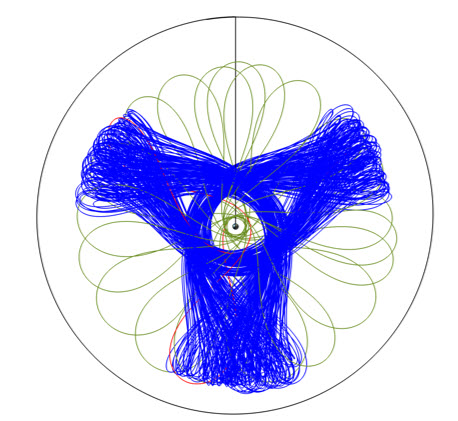
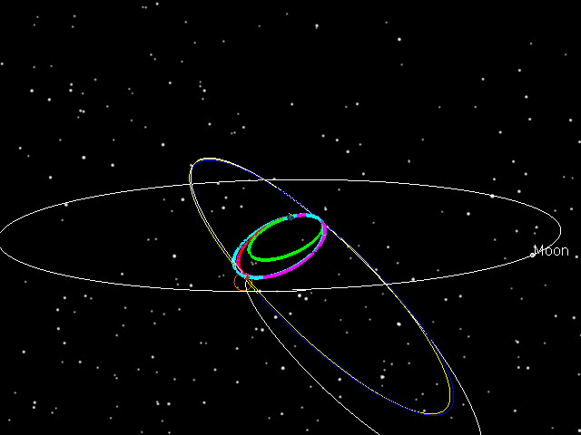
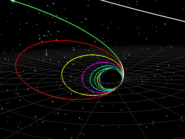
The final extended mission orbit for IBEX is shown in Figure 3 (another rotating view) which has an orbit period that is 1/3 of the Moon’s period. Note that the final orbit (in blue) has apogees that keep clear of the Moon.
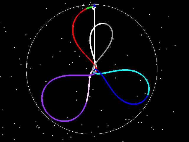
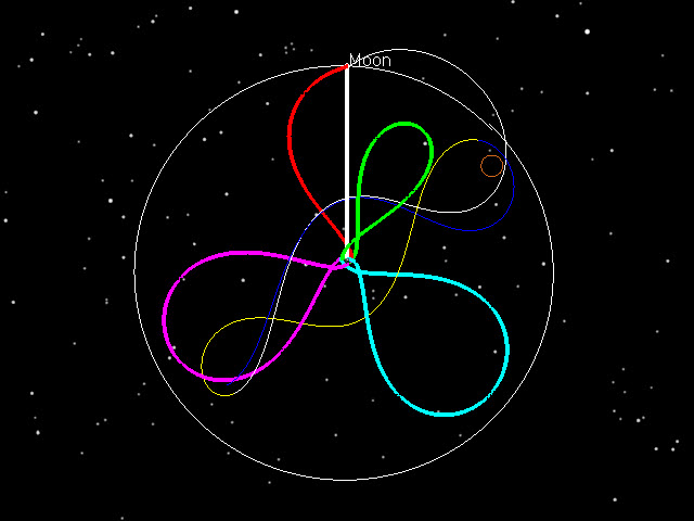
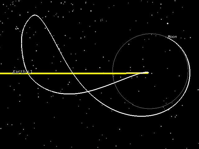
The Lunar Atmosphere and Dust Environment Explorer (LADEE) flew in 2013 and spent 6 months in lunar orbit. The cislunar portion of the mission consisted of 3.5 phasing loops, which extended the launch window and reduced the delta-v requirements of the mission. Figure 4 shows the Earth-Moon rotating view of the trajectory, while Figure 5 shows the inertial view. SEE worked closely with NASA Ames Flight Dynamics personnel to design the trajectory and then execute it in operations.
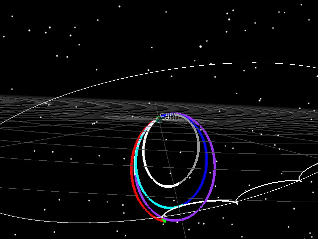
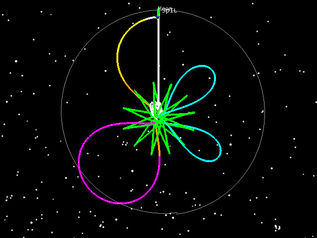
The Transiting Exoplanet Survey Satellite (TESS) launched in 2018 and used a combination of phasing loops (3.5) and a 2:1 resonant orbit, combining features of both IBEX and LADEE trajectories. SEE personnel worked with GSFC engineers to design and fly the mission. Figures 6 and 7 show the phasing loops once again.
In February of 2019, the SpaceIL “Beresheet” lander used a lower starting point with a super-GEO GTO with an apogee near 60,000 km altitude. A series of initial phasing orbits at lower altitudes then had been used on LADEE or IBEX) were necessary. SEE helped design the trajectory, trained the SpaceIL and Israel Aerospace Industries (IAI) Flight Dynamics engineers, and supported them during operations. Figures 8 and 9 show the cislunar portion of the Beresheet trajectory.
The CAPSTONE launch provides a different challenge, as the Electron rocket leaves the Photon + Capstone pair in a really low Earth orbit. We have to do a series of fairly big maneuvers to raise apogee, while giving ourselves enough time between burns to find out how the maneuvers performed, and plan the next one. All of this goes on while the perigee and RAAN are moving due to the Earth’s gravity field. Note that in Figure 10, the starting orbits are really small, compared to starting orbits we’ve used in previous missions.
Figure 11 shows the 7 levels that are used to get to the final targeted asymptote. Finally, Figure 12 shows the same trajectory in an Earth Inertial frame. While the figures don’t show it, there is typically 12 hours or more between each burn, and the entire sequence takes roughly 6 days after launch to achieve.
Once the CAPSTONE spacecraft is precisely placed on its target asymptote by the Photon stage, it is then on a Ballistic Lunar Transfer from which it will approach the Moon and enter into a Near Rectilinear Halo Orbit (NRHO). Figure 12 shows the Ballistic Lunar Transfer CAPSTONE uses to transit to the Moon in an Earth-Sun rotating frame. Finally, Figure 13 shows the same trajectory in an Earth Inertial frame. The BLT and NRHO portion of the mission were planned by our friends at Advanced Space in Colorado. Please visit their page for extensive details of the CAPSTONE Mission:
To provide the best experiences, we use technologies like cookies to store and/or access device information. Consenting to these technologies will allow us to process data such as browsing behavior or unique IDs on this site. Not consenting or withdrawing consent, may adversely affect certain features and functions.
Functional
Always active
The technical storage or access is strictly necessary for the legitimate purpose of enabling the use of a specific service explicitly requested by the subscriber or user, or for the sole purpose of carrying out the transmission of a communication over an electronic communications network.
Preferences
The technical storage or access is necessary for the legitimate purpose of storing preferences that are not requested by the subscriber or user.
Statistics
The technical storage or access that is used exclusively for statistical purposes.The technical storage or access that is used exclusively for anonymous statistical purposes. Without a subpoena, voluntary compliance on the part of your Internet Service Provider, or additional records from a third party, information stored or retrieved for this purpose alone cannot usually be used to identify you.
Marketing
The technical storage or access is required to create user profiles to send advertising, or to track the user on a website or across several websites for similar marketing purposes.